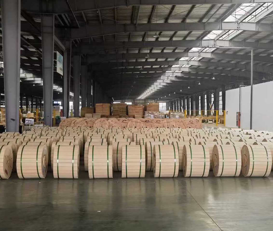
 Optical Fiber
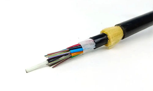 ADSS Fiber Optic Cable
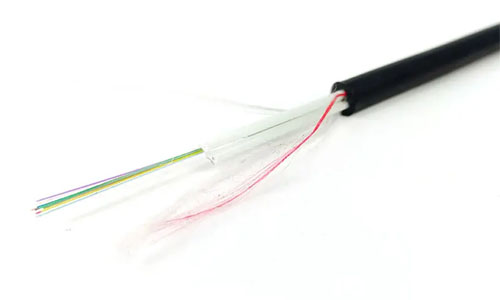 ASU Fiber Optic Cable
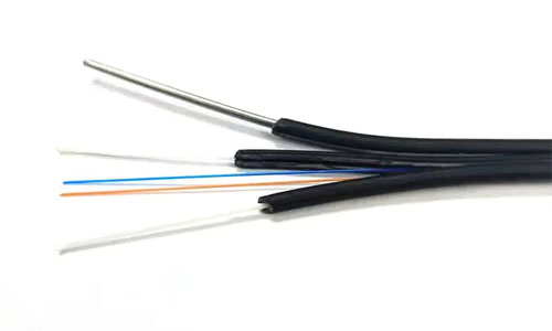 FTTH Fiber Optic Cable
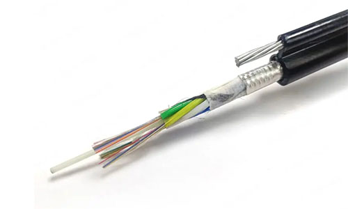 Figure 8 Fiber Optic Cable
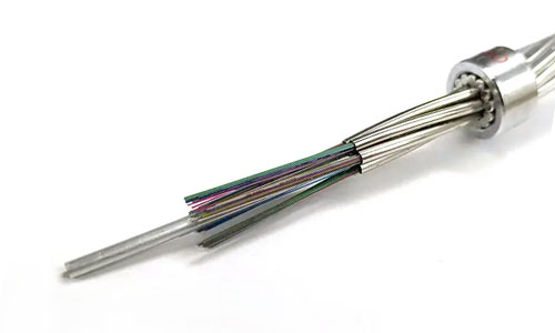 OPGW Fiber Optic Cable
 Coaxial Cable
 Ethernet Cable
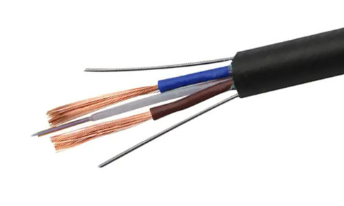 Photoelectric Composite Fiber Optic Cable
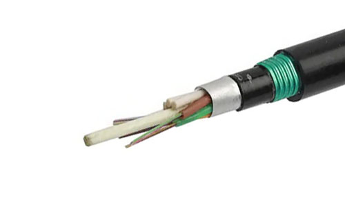 Underground & Pipeline Fiber Optic Cable
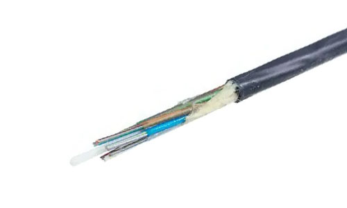 Air-Blown Micro Fiber Optic Cable
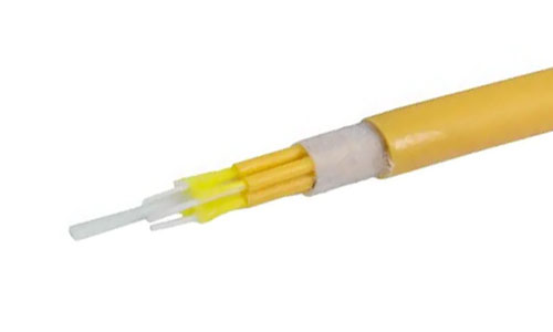 Indoor Fiber Optic Cable
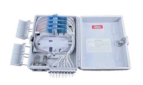 Fiber Optic Distribution Box
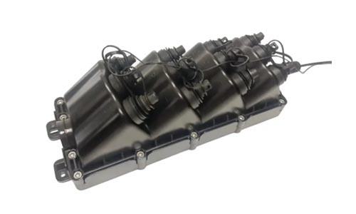 Multiport Service Termina Box
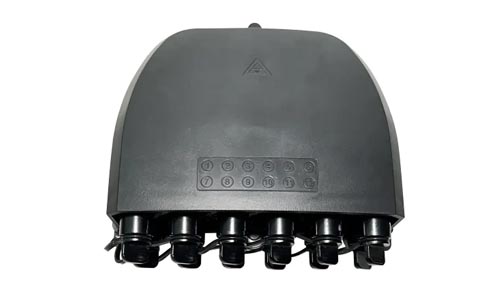 Fiber Optical Terminal Box
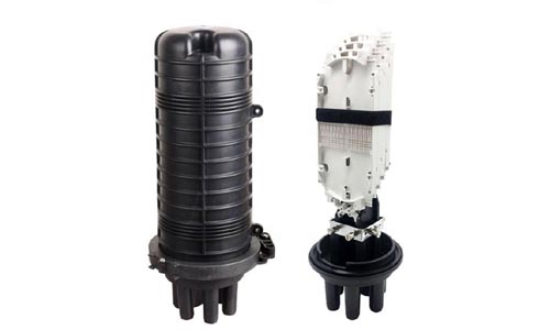 Fiber Optic Splice Closure
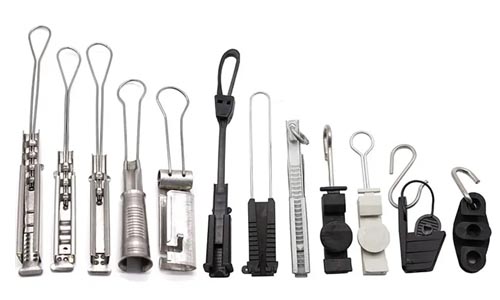 Fiber Optic Clamps
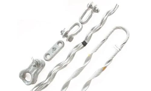 Fiber Optic Cable Fittings
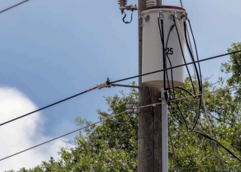 ADSS Fiber Cable
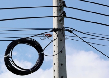 ASU Fiber Cable
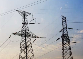 OPGW Fiber Cable
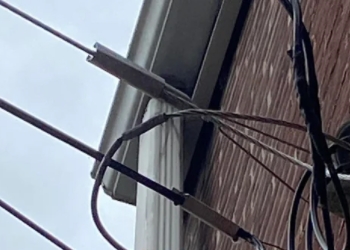 FTTH Fiber Cable
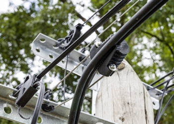 Figure 8 Fiber Cable
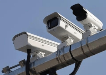 Photoelectric Composite Fiber Cable
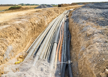 Underground & Pipeline Fiber Cable
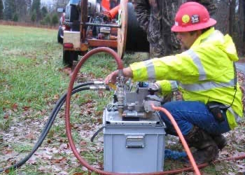 Air-Blown Micro Fiber Cable
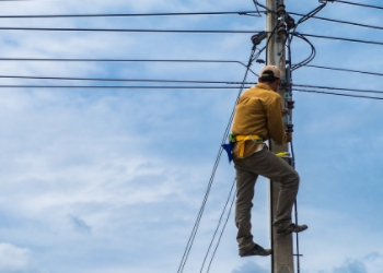 Aerial Fiber Cable
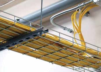 Indoor Fiber Cable
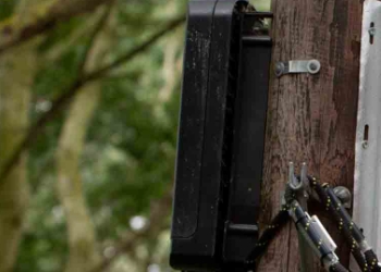 Fiber Optical Terminal Box
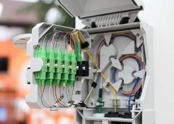 Fiber Optic Distribution Box
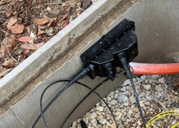 Multiport Service Termina Box
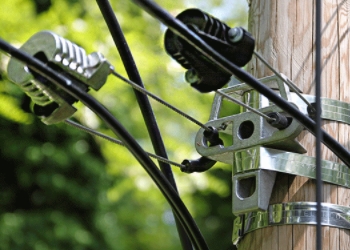 Fiber Optic Clamps
 About Us
 Our Team
 History
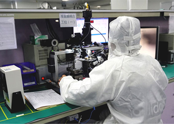 R&D Strength
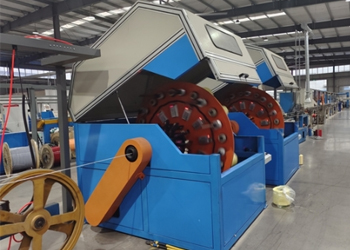 Production Base
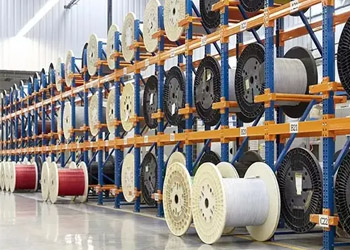 Warehouse & Logistics
 Quality
 FAQs
FAQsWhat is an Optical Time Domain Reflectometer (OTDR)?
Contact for Free Quotation & Sample, According to your needs, customize for you.
inquiry nowWhat is an Optical Time Domain Reflectometer (OTDR)?
OTDR, or Optical Time Domain Reflectometer, is an important tool to locate faults, bends, or breaks in fiber optic cables. It’s a simple device, really, consisting of a laser that sends a light pulse through the cable. Then, it tests how the light reflects, showing where there are problems.
As a result, OTDRs are widely employed by U.S. Cable companies and data centers to ensure lines remain clear and fast. The compact little device is easily carried in a computer bag. It performs exceptionally in challenging environments, such as congested metropolitan back alleys and arid industrial environments.
Many techs in cities such as New York are using OTDRs on a daily basis to increase repair speed and reduce downtime. Whether it’s establishing new networks or repairing existing lines, OTDRs play a key role in maintaining fiber systems’ resilience and reliability.

What Is An OTDR?
An OTDR, short for Optical Time Domain Reflectometer, is an indispensable instrument for testing and troubleshooting fiber optic cables. It’s a useful tool for identifying faults, bends, and breaks along a fiber line. It accomplishes this by sending pulses of light down the fiber and measuring how the light reflects back.
For network engineers managing large metro city networks or complex, long-haul metro or global cables, OTDRs are essential for ensuring uptime and operational efficiency.
1. Light Echoes: The Basic Idea
As an OTDR transmits a short light pulse down a fiber optic cable, the pulse of energy creates reflections. A portion of that light is scattered back toward the device. We refer to this phenomenon as backscattering.
You will see a simple echo in the signal. Then, boom, a spike in light—called a Fresnel reflection—shows up every time there’s a connector or a hard edge. By monitoring these echoes, OTDRs have the ability to detect splices, connectors, and even hairline fractures.
How the light bounces and fades shows how clean the cable is or if it has loss. Moreover, it lets techs holistically know the quality of their fiber by seeing real, quantifiable numbers.
2. Inside an OTDR: Key Parts
An OTDR usually uses a laser or LED as the light source. It consists of a detector to capture echoes and a processor that converts those readings into a visual representation.
It would have a screen to display the trace, and convenient adapters to connect various cable formats. Quality connectors and interfaces make it easier to maintain accurate and fast tests.
3. How OTDRs "See" Fiber?
The OTDR is a fiber technician’s most valuable tool because of their ability to “see” what is going on inside the fiber optic cable. This allows it to identify issues within a foot’s distance.
If the fiber has microbends or contamination, the trace develops dips or spikes. The resulting shape and timing of the light echoes reveal precisely where their fiber is broken and what’s broken.
4. Why OTDRs Are Essential?
OTDRs make it easy to identify faults quickly and maintain a healthy network. They make routine, preventative checks easier and help prevent small issues from developing into larger, more costly issues.
Fast, dependable fiber means more people can stay connected and expensive, disruptive outages are reduced.
Mastering OTDR Traces & Settings
Understanding OTDR traces is the root of good fiber testing. As a visual log of light traveling through the fiber, each trace will depict every event—positive or negative—along its path. Those traces are more than just lines and peaks — each trace is a snapshot of what’s happening inside the cable.
If interpreted correctly, you can see not only splices and connectors, but other tricky problems such as ghosts or dead zones. Choosing optimal settings matters just as much. A pulse width or index of refraction mismatch can lead to inaccurate readings.
This difference is significant when you’re looking for actual figures not estimates! The better your trace analysis, the fewer surprises you’ll have. It provides more dependable connections, whether you’re in the field with long-haul fiber cables or short LAN links, where unseen events can truly make a difference.
Reading the Fiber's Signature
Those peaks and slopes we see in a trace aren’t just pretty patterns—they represent actual events. A steep spike indicates a reflective event, such as a connector or a fiber break. Smooth dips or rises could be interpretable as splices, bends, etc.
When you see a flat slope, this indicates the fiber is in good condition and a steep slope indicates loss or stress. Identifying these signatures allows you to correct issues quickly, such as a kinked fiber or incorrect splice. When you know what’s normal for your cable, you’ll have an easier time spotting trouble before it becomes a problem.
Identifying Key Fiber Events
Identifying Key Fiber Events comes down to identifying their shape and location on the timeline. Each one alters how signals propagate, impacting link performance and consistency.
The time spent tracking and documenting each event is worth it when it’s time to conduct repairs or upgrades. Key events to look for include:
-
Connectors
-
Splices
-
Breaks
-
Bends
-
Ghosts
-
Dead zones
Smart Test Parameter Choices
Choosing the correct pulse width, wavelength, and index is key to receiving clear, true results. A short pulse picks up small events in short runs, while a long pulse works for long-haul without missing key details.
Change parameters based on the application and fiber category. High-quality connectors, which aren’t always available on launch cables, are imperative. Always test both directions for the entire truth.
For difficult to locate losses, set your attenuation properly to prevent missing a loss.
Pulse Width and Wavelength
Pulse width impacts your trace, and it can impact what you see. Skinny pulses catch fine details but can miss deep in the cable, while wide pulses travel farther but blur close events.
Wavelength—This is important—850nm and 1300nm for multimode, 1310nm and 1550nm for single-mode. Every setting decision plays a role in detecting stress points or kinks and ensuring your data are accurate.
Index of Refraction & Averaging
The index of refraction, or n-value, is the speed of light in the glass. If you don’t set it properly, your trace will not reflect the actual length of the cable.
Averaging reduces noise and creates a clearer trace. Get these settings dialed in, and you’ll have faith in your results—particularly when measuring loss or strange return reflections.
OTDRs in Real-World Use
Fiber optic networks across the U.S. Are essential in keeping our hospitals and data centers open and connected. OTDRs, or optical time-domain reflectometers, as they are known, play an invisible role in all these locations. They provide crews a realistic view of what’s going on inside the cables.
As networks grow, OTDRs become necessary to address work that simple Tier 1 test will not catch. In addition, they allow for critical repairs and maintenance to be done when necessary.
Certifying New Fiber Networks
When a new fiber link is constructed, OTDRs are used to ensure that each splice and connector falls within spec. They do more than measure overall loss, identifying subtle events such as dirty end faces or bends in the fiber.
Crews conduct tests at various wavelengths—such as 1310 and 1550 nanometers on single-mode lines—to identify potential stress points. They use data from OTDRs to check metrics such as reflectance and event loss.
Having launch fiber of at least 350 feet allows you to test the first connector. True end-to-end testing involves testing in both directions—bi-directional testing—to provide accurate information.
Rapid Fault Pinpointing Saves Money
When a line is broken, OTDRs indicate exactly where the break or poor splice is located. That reduces the amount of time they’re down for repairs and saves on repair bills.
For instance, an OTDR tech can identify a kink or macrobend and then repair only that point. This more precise remedy translates into less disruption and lower danger of service loss.
Proactive Maintenance Benefits
Routine OTDR checks identify the early warning signs—such as increasing loss or new microbends—before they develop into major failures. This allows teams to proactively plan their repairs rather than reactively scrambling in a moment of crisis.
Having robust data available from OTDRs allows planners to create more intelligent maintenance schedules and ensures that networks remain healthy long into the future.
Documenting Your Fiber Plant
Maintaining tidy OTDR records is important. Crews should save trace files, documenting test settings, and producing reports that are clear and understandable.
These files make it possible to repair emerging issues with greater speed and efficiency. They monitor trends as well, which simplifies the maintenance of the entire system.
OTDR vs. Other Fiber Tools
Fiber testing requires more than a single tool, and choosing the right combination can help you succeed. OTDRs, or Optical Time Domain Reflectometers, are superior tools for understanding the lay length of a fiber link. They identify breaks and detect reflective events like connectors or splices.
Other tools have unique advantages. Optical Loss Test Sets (OLTS), Visual Fault Locators (VFLs), and fiber inspection scopes are other examples. In Marrakech, where new fiber lines frequently cut through busy streets and historic buildings, this is especially true. Understanding when to use each tool leads to less surprises and easier installs.
OTDR vs. OLTS: Key Differences
| Feature | OTDR | OLTS |
|---|---|---|
| Function | Maps fiber, finds faults & events | Measures total loss, link length, polarity |
| Output | Trace (graph with distance & events) | Pass/fail reading, loss in dB, length in feet |
| Fault Location | Pinpoints breaks, bends, splices | Doesn’t show fault location |
| Use Case | Tier 2 certification, troubleshooting | Tier 1 certification, basic acceptance tests |
| Limitations | Can miss subtle loss, learning curve | No event pinpoint, can’t see all faults |
OTDRs truly become valuable when you need insight into the link, identify specific fault locations, or inspect splices. Unlike an OTDR, an OLTS provides fast, easy-to-interpret results that are ideal for pass/fail testing.
When to Use Each Tester?
Technicians turn to OTDRs when they need to map long runs, find fiber breaks or test bends in hard-to-access locations. OLTS is ideal for certifying new links or verifying loss and polarity.
In large metropolitan city networks, both are heavily utilized—initially OLTS for a quick pass/fail test, then OTDR for troubleshooting and more advanced analysis.
Combining Tools for Best Results
We recommend that you use OTDRs, OLTS, and scopes together for best results. For example, use OLTS to check the total loss, OTDR to locate the break, and a scope to see if the connector’s dirty.
Used in combination, however, they significantly increase the speed and accuracy of fault finding.
Navigating Common OTDR Challenges
Working with OTDRs does come with plenty of challenges, particularly when it comes to field deployments in everyday fiber optic networks. It’s a common misconception that techs in the field often only want to check fiber links from one end. Good performance can only be assured with bi-directional testing!
A loop on the other end is used by many teams. This means they can test in both directions simultaneously while significantly reducing the number of steps involved.
Understanding Elusive Dead Zones
Understanding Elusive Dead Zones Dead zones can fool even the most advanced technology. These are brief segments immediately following a connection or splice where the OTDR is unable to detect individual events.
This event dead zone, typically around 10–65 ft, can cause nearby faults to remain concealed. Using longer launch fibers, up to 350 feet, gets the first connection out of the dead zone.
This one change provides visibility into the underlying cause. Detecting these elusive dead zones is critical when interpreting traces. This way, you won’t overlook a connector defect or splice lurking in the smudge!
Dealing with "Ghost" Reflections
Dealing with “Ghost” Reflections Ghost reflections show up when light is reflected back and forth within the fiber. These reflections cause the appearance of “ghost” events on your OTDR display.
They can be deceiving, as they usually appear as if they are real faults, yet do not correlate to physical defects. To reduce the chances of creating ghosts, ensure that connectors are clean and properly mated.
If a reflection is high—meaning it is close to 0 dB—it typically indicates a poor connection in the immediate vicinity. Understanding how genuine and ghost events appear is key to ensuring that you don’t misinterpret your analysis.
Maximizing Measurement Accuracy
Achieving reliable numbers from an OTDR begins with calibration and selecting the appropriate wavelength for your fiber. U.S. Military and government standards mandate using launch and receive fibers.
They further recommend avoiding bends and stress on cables and inspecting connectors before each test. Let’s not forget testing conditions—a controlled, clean environment will always yield superior results.
Interpreting Complex Trace Data
OTDR traces can appear as intimidating as a mountain range to the uninitiated. Look for clear steps: the launch point, connectors, splices, and the fiber end.
Patterns—such as a sudden spike or dip—could indicate a fracture or a sharp curve. With a little bit of trial and error, understanding these traces becomes second nature.
Before you know it, you’re identifying issues before they turn into major failures.
Choosing Your Ideal OTDR
Finding the perfect OTDR is going to be one of those tasks that is very similar to choosing any tool for a specific job—every little thing counts! In the quick-moving field of fiber optics, an incorrect fit can cause lost productivity or even rework. Fiber networks span the most congested cities in the country and reach out to the rural communities. For field technicians and engineers, the OTDR has proven itself to be an indispensable tool.
Match OTDR to Network Needs
When selecting an OTDR, consider the following factors:
-
Fiber type (single-mode vs. multi-mode)
-
Network size and cable length
-
Application type (troubleshooting, certification, maintenance)
-
Wavelengths needed (850nm, 1300nm, 1310nm, 1550nm, 1625nm)
-
Operational environment (indoor, outdoor, harsh conditions)
Large metropolitan networks across the United States require OTDRs that can efficiently process long runs and dense cables. Some small office links may require just a few short-range tests. If you’re deploying single-mode fiber, your OTDR should be up to the task. Multi-mode requires a different beast altogether. For multi-faceted jobs, a dual-mode device can reduce time and eliminate frustration.
Critical Specs: Range, Resolution
Look at the dynamic range to determine your distance measurement requirements. The larger the range, the farther spans you’ll be able to test—rural installs vs city blocks, for instance.
Resolution refers to the minimum distance between two faults that can be resolved—they would otherwise appear as one if too close together. A high resolution is essential for identifying elusive faults situated very close to one another. No one likes a dead zone—smaller is better for locating consecutive faults.
Field Portability Considerations
Field portability considerations are crucial. In the field, weight and real-estate are extremely important factors. A durable OTDR with a reliable battery makes long days and small spaces more manageable.
Bottom line, rugged casings with straightforward screens make a difference on stormy days or in low light conditions. If you’re climbing poles or crawling in basements, easy-carry gear ensures the efficiency of labor.
Future-Proofing for US Networks
New technology continues to emerge and fiber standards continue to expand. Choose OTDRs that can manage both legacy and current wavelengths so you’re not left behind.
Models that ensure an easy upgrade path, or are flexible through software support, will pay dividends in a time when networks are inevitably shifting. Versatile equipment leads to less overall replacement and greater uptime.
Conclusion
When used strategically, OTDRs are a crucial tool in ensuring fiber lines remain robust and reliable. People in the field rely on them to locate faults, test splices, and maintain networks with precision. From major metropolitan areas to rural communities, technicians depend on OTDRs to help them rapidly pinpoint issues. They repair these problems long before residents start calling with complaints about slow internet. Choose the right OTDR, and the work only becomes more manageable, not more difficult. From interpreting those devilish traces to preparing for the next attempt, each part of the process gets a little bit easier with repetition. Have a team new to the field or just looking to sharpen your skills? Join us, trade anecdotes, figure out what’s actually working in the world and share it. With good tools and smart hands, those signals will keep flowing strong. Until then, continue to learn, stay creative, and don’t let those logistical lines get too fuzzy!
Frequently Asked Questions
What does OTDR stand for?
What does OTDR stand for & what is an OTDR It is an essential instrument in the testing and maintenance of fiber optic cables.
How does an OTDR work?
Simply put, an OTDR sends pulses of light down a fiber and measures all the light that gets reflected back. This makes it easy to trace faults, splices, and bends along fiber optic cables.
Why is OTDR important for fiber networks?
As a result, OTDRs allow technicians to accurately pinpoint faults and troubleshoot issues with remarkable speed. This results in quicker repairs and improved high-speed internet and communication services.
Can an OTDR test all types of fiber optic cables?
Can an OTDR test all types of fiber optic cables? In short, you need to know how to choose the appropriate testing parameters based on the cable type being tested.
What is an OTDR trace?
What is an OTDR trace? Most importantly, it aids technicians in identifying any problems such as breaks, splices, or excessive bending.
How is an OTDR different from other fiber testing tools?
Unlike standard testers, an OTDR delivers comprehensive distance and location information for failures. It provides a visual representation of the entire fiber, rather than just end-to-end loss.
What should I consider when choosing an OTDR?
Look at the fiber type, test range, wavelength choice, and user-friendliness. Ensure that the OTDR is appropriate for your network’s requirements and your team’s experience level.