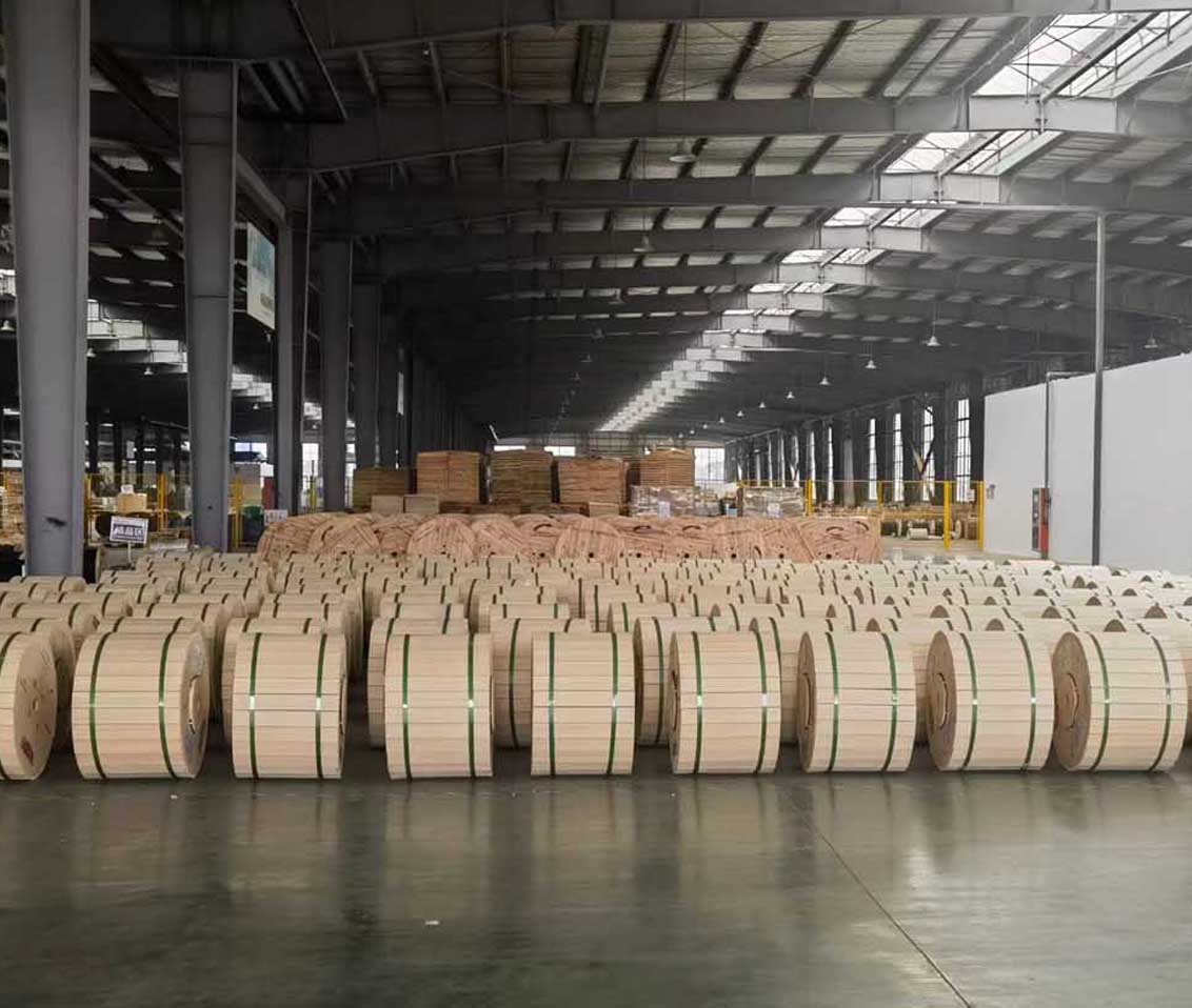
 Optical Fiber
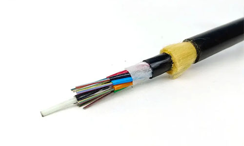 ADSS Fiber Optic Cable
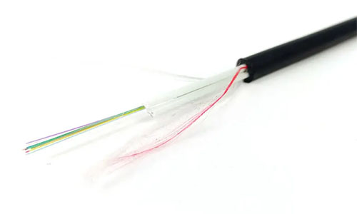 ASU Fiber Optic Cable
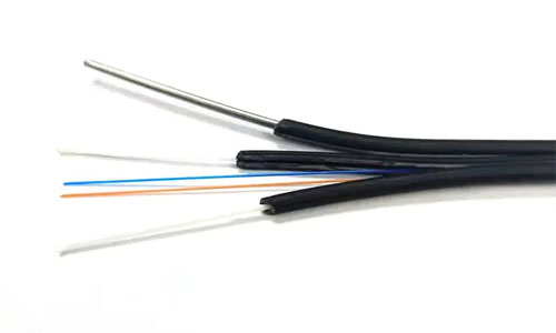 FTTH Fiber Optic Cable
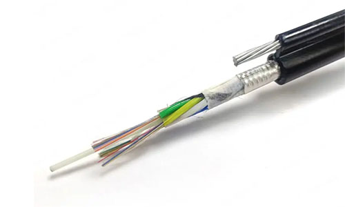 Figure 8 Fiber Optic Cable
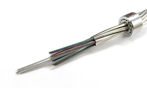 OPGW Fiber Optic Cable
 Coaxial Cable
 Ethernet Cable
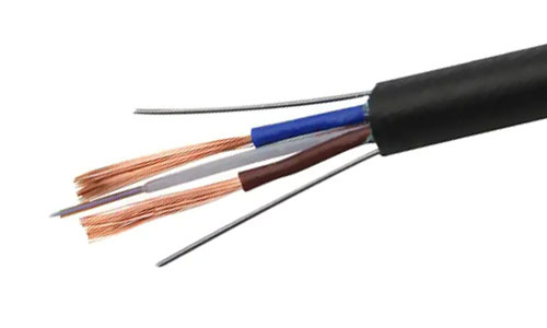 Photoelectric Composite Fiber Optic Cable
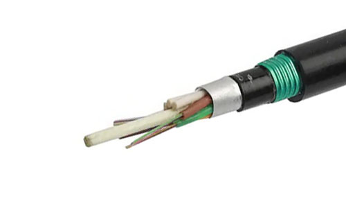 Underground & Pipeline Fiber Optic Cable
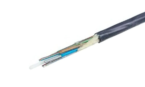 Air-Blown Micro Fiber Optic Cable
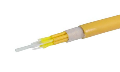 Indoor Fiber Optic Cable
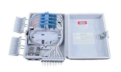 Fiber Optic Distribution Box
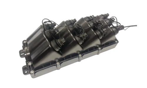 Multiport Service Termina Box
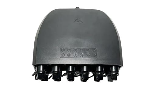 Fiber Optical Terminal Box
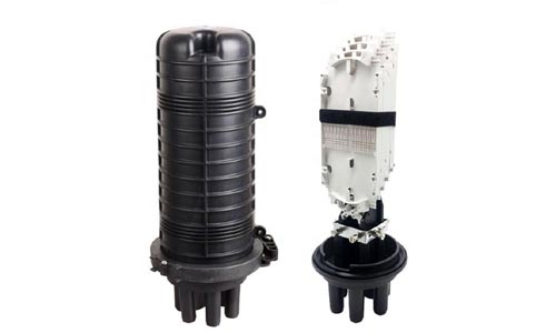 Fiber Optic Splice Closure
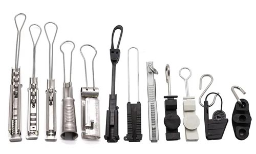 Fiber Optic Clamps
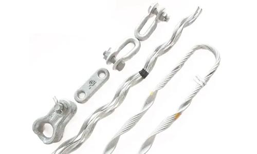 Fiber Optic Cable Fittings
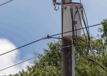 ADSS Fiber Cable
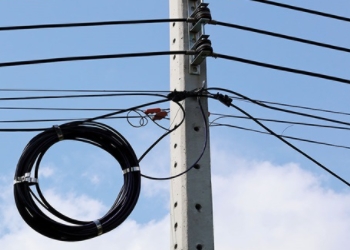 ASU Fiber Cable
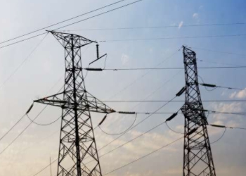 OPGW Fiber Cable
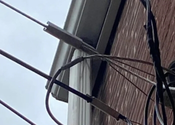 FTTH Fiber Cable
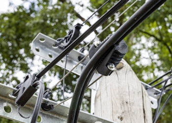 Figure 8 Fiber Cable
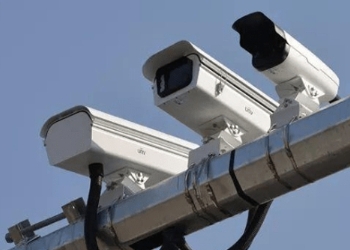 Photoelectric Composite Fiber Cable
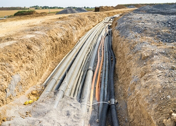 Underground & Pipeline Fiber Cable
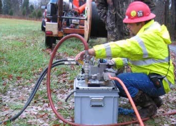 Air-Blown Micro Fiber Cable
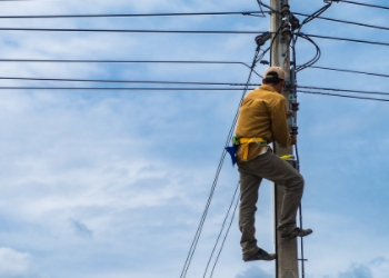 Aerial Fiber Cable
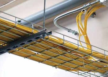 Indoor Fiber Cable
 Fiber Optical Terminal Box
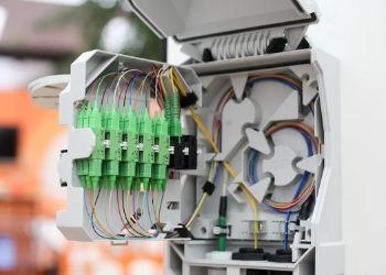 Fiber Optic Distribution Box
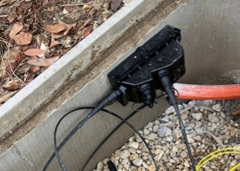 Multiport Service Termina Box
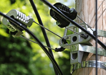 Fiber Optic Clamps
 About Us
 Our Team
 History
 R&D Strength
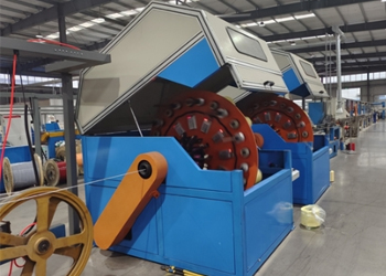 Production Base
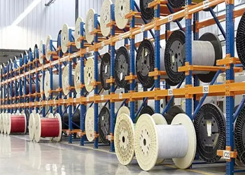 Warehouse & Logistics
 Quality
 FAQs
FAQsUnderstanding Optical Time Domain Reflectometer (OTDR) and Its Applications
Contact for Free Quotation & Sample, According to your needs, customize for you.
inquiry nowUnderstanding Optical Time Domain Reflectometer (OTDR) and Its Applications
An Optical Time Domain Reflectometer (OTDR) is a fundamental piece of equipment for troubleshooting and maintaining fiber optic networks, detecting faults, and verifying quality of connections.
By dispatching light pulses along fibers and quantifying reflected signals, OTDRs assist in identifying faults, splice losses, and other concerns that may affect network efficiency.
Knowing how to interpret OTDR trace data, from reflections to loss profiles, is essential for troubleshooting and tuning fiber optic links.
Critical performance factors like dynamic range, pulse width and dead zones impact the precision and dependability of OTDR readings, so it’s important to choose the correct configurations for every situation.
OTDRs are essential for network certification, fault location and proactive maintenance, enabling technicians to keep track of fiber health and avoid expensive downtime.
While both experts and non-experts can learn to operate OTDRs, such equipment-specific training gives you a more accurate analysis, which is crucial for long-term network reliability.
An optical time domain reflectometer (OTDR) tests the integrity and length of fiber optic links by shooting pulses of light into the fiber and measuring the light that reflects back. OTDRs assist locate breaks, bends, and bad spots in the cable by indicating where signal loss occurs. Most OTDRs use a small screen to display a basic trace so you can identify trouble spots immediately. Easy to carry and often used in the field, OTDRs assist individuals in maintaining fiber networks without excessive conjecture. Many network technicians reach for OTDRs for routine care and rapid repair. The following section will demonstrate how OTDRs function and why they’re important in typical fiber arrangements.

What is an OTDR?
OTDR (Optical Time Domain Reflectometer) A device to test and characterize light transmitted in fiber. It’s primarily utilized to detect faults or vulnerabilities in fiber optic cables by pulsing short laser bursts down the fiber and measuring the amount of light reflected back. This assists in locating faults, contamination, or fractures, and indicates loss of signal strength over distance. Testers use OTDRs to test splice loss, fiber attenuation, and maintain fiber networks.
1. The Core Function
The core business of an OTDR is to troubleshoot fiber networks. When there’s a cut or kink in the fiber, or if connectors are dirty, the OTDR can highlight exactly where the issue lies. This is important to maintaining dependable fiber networks, because minor problems fester into major headaches if left unattended. By catching issues early, the OTDR helps avoid larger outages and keeps information flowing quick and secure.
Precise OTDR readings are the trick. Even a tiny miscalculation can lead a tech to repair the wrong location—or overlook an actual issue entirely. That’s why techs count on the high resolution of today’s OTDRs, which can distinguish two events separated by mere centimeters.
2. The Light Pulse
Each OTDR test begins by blasting a strong, short pulse into the fiber. This pulse is your starting whistle, and its shape, intensity, and length all count. A powerful, narrow pulse will go further and discover minute defects. If it’s too long, it might overlook very short gaps or small breaks. Juggling these pulse characteristics is a large part of OTDR usage well.
As the pulse of light journeys it encounters varying objects—splices, connectors, dirt, or even tight bends. Each event alters the light slightly. The OTDR detects these variations and leverages them to reconstruct what’s occurring within the cable.
3. The Reflection
When the pulse strikes something within the fiber, some of it reflects back towards the OTDR. This is known as backscatter—the most prevalent being Rayleigh backscattering. The device measures how much light returns and when. Fresnel reflections present themselves, typically from joints or connectors, and these provide sharp spikes in the trace.
Through observing the reflected light and the intensity of such reflections (known as the reflection coefficient), customers can determine whether the fiber is clean, the splices are perfect, or if a break exists.
4. The Time Measurement
The OTDR observes the precise time when light returns. It converts time into distance, so a technician can determine how far down the fiber a problem is located.
Time is everything for precision. If the timing circuit isn’t precise, the fault location can be way off. Better OTDRs have exact clocks to keep these measurements tight.
5. The Distance Calculation
The OTDR then figures out how far the light pulse traveled before returning. This becomes a map of the fiber–where all the connectors, splices and faults are.
This distance is important to get right because it directs repairs. If you know it’s 1,500 meters down the line, you don’t have to guess where to dig or pop open panels. Convenient for large systems and extended cables.
How an OTDR Works?
An OTDR sends a brief pulse of light down a fiber optic cable, and then listens for light that reflects back. This results in a map of loss and reflections, assisting technicians in identifying faults or potential weak points in the cable.
Rayleigh Scattering
Rayleigh scattering is when microscopic impurities in the glass fiber disperse light in every direction. The OTDR detects a small fraction of this scattered light—roughly one part per million—returning to its detector. This backscatter is crucial for the OTDR to observe what’s going on all throughout the cable’s length.
Rayleigh scattering is, in fact, the fundamental source of signal attenuation in a fiber. As light in the fiber propagates, some energy is dissipated in scattering, so that attenuated signal arrives at the far end. By quantifying the returned light, the OTDR can indicate whether the fiber is healthy or if there are areas of elevated loss. The more precise the measure of Rayleigh backscatter, the more effectively the OTDR can detect minor variations or faults in the fiber.
Fresnel Reflection
Fresnel reflection occurs at any abrupt interface where the material changes, such as a fiber connector or break. This spike makes a distinct, sharp spike on the OTDR trace that rises above the smoother Rayleigh background. If two fibers are spliced with a micro air gap, for example, a difference in refractive index can cause light to leap immediately backward. That’s why splices or breaks are so obvious on a trace.
Seeing a high reflection, for example, can indicate trouble — like a bad connector or a break. At a fusion splice, where fibers are welded, there’s nearly no reflection, so the trace remains flat. Understanding how to interpret these spikes can assist users in identifying the precise location of a fault. Fresnel reflections are key for testing connection quality, and can indicate if additional cleaning or re-termination is required.
Visual Trace and Analysis
The OTDR captures this return light and maps it on a display, or trace. The x-axis indicates distance along the fiber and the y-axis indicates power level. Each dip or spike on this trace narrates a legend—a splice, fault, or attenuation site.
This map allows users to spot problems at a glance. The trace can help direct repairs, monitor fiber condition and verify cables are terminated properly. Having the ability to “see” inside the fiber without terminating it is what makes the OTDR so useful.
Key Performance Metrics
The worth of an OTDR boils down to some key performance metrics. These determine how well it can detect bugs, how deeply it can fuzz, and whether it suits specific tasks. End users, regardless of their professional environment, consult these numbers when selecting an OTDR for routine fiber work.
-
Dynamic range (dB): shows the farthest length the OTDR can test
-
Measurement range: links to dynamic range, sets max cable length for full results
-
Pulse width: sets how close events can be and still be seen apart
-
Dead zones: the areas where faults can't be found, measured in meters
-
Instrument resolution: how well it spots events that are close together
-
Number of test wavelengths: tells what types of fiber the tool can check
-
Multi-port testing: if it can check more than one fiber at a time
-
Optical filter: useful for live fiber testing and signal protection
-
Return loss/reflectance: tells the quality of the fiber connections
Dynamic Range
Dynamic range refers to the distinction between the most powerful backscattered signal and the background noise. It’s measured in decibels. Greater dynamic range allows the OTDR to detect weak reflections from distant fiber terminations. This identifies minor issues that can cause problems down the road. On long fiber runs, say undersea cables or wide networks, dynamic range is what allows users to see the far end clearly. The higher this value is, the better network checks it performs, fewer faults it misses, and more reliable people think it is.
Pulse Width
Pulse width is the duration of the light pulse transmitted by the OTDR. Shorter pulse widths increase instrument resolution, allowing the device to detect closely spaced events, such as splices or connectors only a few centimeters apart. Shorter pulses mean less range because the signal is weaker, so there’s a tradeoff. Longer pulses allow you to test further but sacrifice detail. Picking the right pulse width is a balance: short for detail, long for distance. This selection defines how the OTDR composes to a job–be it mapping dense data centers or long telecom lines.
Dead Zones
Dead zones are blind spots following a hard reflection, where the OTDR cannot detect additional events. These gaps are a result of the photodetector becoming saturated. They appear as swaths where a splice or kink could slip past unnoticed. Too large a dead zone, and the OTDR skips over important faults. Good OTDRs employ clever pulse shaping and fast recovery to reduce these regions. Small dead zones translate to more precise, more actionable testing, especially in networks with many congested connectors.
Interpreting an OTDR Trace
An OTDR trace is a visual readout of how light travels through a fiber. Knowing how to read this trace is essential for fault location, loss measurement, and splice and connector inspection. Each dip, rise or flat spot on the graph represents a story about the fiber’s health. By learning to identify dead zones, pulse width, and event tables you can locate and repair issues quickly.
The Starting Pulse
The leading pulse is the initial blast of light introduced to the fiber. This pulse establishes the background for the rest of the trace. If narrow, it offers increased resolution, allowing you to distinguish two nearby events. A broader pulse flattens the trace, which is helpful when the fiber is long or events are widely separated. The integrity of this pulse foreshadows the fiber’s initial status; therefore, any unusual form may indicate issues precisely at the launch. If you see a large spike or an unusual spike, inspect your launch cable/connection.
The Fiber Span
The fiber span is simply the length of cable under test. Its length determines your resolution in judging event-to-event distances in the trace. Assuming you understand the precise span, you can see where losses or breaks occur. Both by a nice, steady drop in the graph, indicating that light is moving through the fiber with normal loss, due to Rayleigh backscattering. A dead zone frequently appears immediately following the launch pulse, where the detector is saturated by reflected light. The span needs to be long enough to cover all portions you wish to examine, but not so long that you overlook minor occurrences.
The Splice Loss
Splice loss is a big deal to maintaining strong signals. Every splice, where two fibers come together, can cause a dip in the trace. These dips appear as small steps or discontinuities. OTDRs make it easy to identify bad splices by the size of the drop—larger indicates greater loss. If you keep splice loss in check, you keep the network humming. When splices get untidy, you experience high loss. That is your signal to re-terminate the joint.
The Connector
Connectors connect cables, however they can be problematic. A bad connector might display a spike or dip in the trace. The reflection value, in dB, indicates how powerful the signal is that bounces back. A high value (near 0 dB) usually indicates a bad connection or dirty end. OTDRs help you identify leaky connectors so you can scrub or swap them. Being aware of the connector types and status for each one of them makes your tests more incisive.
The Fiber End
The fiber end is where the light ultimately terminates. If the end is clean, the trace ends with a nice, crisp drop. A sloppy or fractured end produces a fuzzy, irregular fade. Always examine this section for a ‘good’ break or overly strong reflection. If you spot a large Fresnel, time to clean or re-cut the end.
Practical Field Applications
OTDRs are a staple on many fiber optic field jobs. They’re not only loss testers, they’re assisting in network design, quality assurance, preventive maintenance and troubleshooting. This makes them an essential instrument for the fiber professional, from massive carrier architectures to tiny local configurations. Their application ranges from basic verifications to complex compliance tasks according to international criteria.
-
Certification of fiber networks to degree of Tier 2 (TIA) and “extended” (ISO) standards.
-
Diagnosing and characterizing fiber links–identifying defects such as dirty ends, macrobends, microbends and bad connectors.
-
Assisting when with bi-directional tests, as results may vary depending on the test directions.
-
Troubleshooting live network issues fast to cut downtime.
-
Launch fibers (typically 350 feet or so) to test the initial connector in a link.
-
Recording fiber installs for future tracking and repair.
-
Describing occurrences overlooked by cruder loss measures, making problems easier to identify.
Network Certification
Network certification is the first step for all fiber optic installs. It demonstrates the job conforms to sector standards and functions appropriately. OTDRs for Tier 2 compliance and “extended” ISO checks. These tests go further than loss leader tests. OTDRs display each event – connectors, splices or bends – assisting techs to identify defects and demonstrate that they repaired them.
-
Configure the OTDR with proper parameters for fiber type, wavelength, and test limits.
-
Connect the launch fiber to the link under test.
-
Run the OTDR trace and test every event on the fiber.
-
Test from both ends for bi-directional results.
-
Preserve the trace and contribute it to the web logs.
With OTDRs, each trace provides a snapshot of network vitality—great for audits or new enhancements.
Fault Location
Locating fiber faults quickly, that’s what keeps networks alive. An OTDR reveals where an issue lies, be it a poor splice, damaged fiber, or soiled connector. This is a timesaver because techs don’t have to speculate where the break is or excavate long cable runs.
Rapid fault spotting means less user downtime — which is crucial when working with mission critical links in hospitals or banks. Timely repairs reduce costs, since tiny problems such as microbends can lead to larger-scale trouble if ignored. OTDRs make the job faster by providing a map to the fault, so techs go straight to the location and repair it.
Proactive Maintenance
Proactive maintenance stops problems before they strike. OTDRs assist by testing fiber integrity on a routine schedule. They detect small problems—minuscule kinks, grime, or slack links—prior to these becoming outages.
Periodic challenges keep the network humming. They provide a baseline for comparison over time, so if something shifts, it immediately pops.
-
Schedule regular OTDR sweeps for all fiber routes.
-
Compare old and new traces to spot changes.
-
Use bi-directional tests for full accuracy.
-
Clean and check connectors at every test.
OTDR vs. Other Testers
OTDRs are exceptional in fiber optic testing, providing an alternative method to examine the entire fiber link. Unlike testers, they trace backscattered and reflected light to pinpoint faults, measure distance, and map losses. Other testers, such as OLTS and Power Meters, have more straightforward tasks—measuring power at a location or total loss end-to-end. All of these tools have their place but OTDRs dig deeper—making them critical for those who need more than a surface-level diagnosis.
The Specialist
Specialists deploy OTDRs for comprehensive diagnostics, identifying faults and vulnerabilities that rudimentary testers might overlook. To interpret OTDR trace data, these specialists require an astute eye and hands-on experience. Reading a trace isn’t always clear-cut: Rayleigh backscattering and Fresnel reflections create patterns that need careful study. Without training, a user could overlook a bad connector or confuse a reflection for a fault. That’s why experts typically take deep dive courses, mastering how to configure pulse widths, calibrate event thresholds, and detect subtle shifts in the trace.
Their expertise keeps fiber networks operating optimally and extending their lifespan. By detecting problems in their infancy, the pros keep businesses out of downtime. OTDRs are critical for Tier 2 compliance testing, which is more involved than Tier 1’s basic loss measurements. In the real world, this translates to a network tested by an OTDR-skilled technician less prone to failure at critical moments.
The Generalist
Generalists will use OTDR’s for spot checks or rudimentary troubleshooting, such as locating breaks or bad splices. They may not get into every trace nuance, but knowing the fundamentals—such as how to test from both fiber ends—is still important. Even if their primary role is reactive maintenance, understanding the fundamentals of OTDR testing can equip them to identify serious issues before they deteriorate.
For generalists, minimal training works wonders. Knowing how to setup the OTDR, read easy loss events and compare with OLTS or Power Meter readings keeps the network humming. They might not dig into every setting, but they know enough to do the job right.
| Role | Main Tasks | OTDR Skill Level | Value Add |
|---|---|---|---|
| Specialist | In-depth fault finding, compliance | Advanced | Full analysis, long-term health |
| Generalist | Troubleshooting, basic checks | Basic | Quick fixes, routine maintenance |
OTDR vs. Other Testers: At a Glance
| Tester Type | Main Use | Detail Level | Training Needed | Key Benefit |
|---|---|---|---|---|
| OTDR | Fault finding, full analysis | High (trace, events) | High | Detects hidden faults, maps fiber |
| OLTS | Power loss, polarity | Medium | Low | Fast certs, total loss measurement |
| Power Meter | Power at one point | Low | Minimal | Simple, direct power reading |
Conclusion
OTDRs provide techs a convenient means to test fiber optic cables. These devices transmit rapid light pulses and receive reflections. Crews detect breaks, bends, or grimy joints at high speed. Folks employ OTDRs in the field to repair lines, validate new work, or maintain networks. Unlike antique testers, OTDRs display actual locations and provide a graphical trace, like a map. Any fiber worker knows the time and hassle a good OTDR can save. You got a stubborn line to check or need to stay sharp? Try OTDRs and notice how much simpler the work becomes. For additional pointers or anecdotes from the field, check out the following guide or consult an experienced pro.
Frequently Asked Questions
What is an Optical Time Domain Reflectometer (OTDR)?
What is the optical time domain reflectometer(otdr) It can measure the loss and locate faults along the fiber.
How does an OTDR help in fiber optic testing?
The OTDR transmits light pulses and listens for them to be reflected back. This allows it to find breaks, bends, and other problems in the cable.
What are the main benefits of using an OTDR?
An OTDR gives you precise fault location, rapid diagnostics and comprehensive fiber performance information. It assists in effective fiber network deployment and troubleshooting.
What information can you get from an OTDR trace?
An OTDR trace reveals the fiber’s signal loss, reflective events, splices and breaks. It provides a picture of the fiber’s well-being.
How does an OTDR compare to other fiber testers?
Unlike other testers an OTDR can identify the precise location of faults and provide a comprehensive characterization of the fiber link. It is more sophisticated and descriptive.
What are the key performance metrics for an OTDR?
Important parameters are dynamic range, resolution, dead zones and event detection. These impact the OTDR’s ability to effectively identify and isolate trouble.
Can beginners use an OTDR effectively?
Okay, but aren’t OTDRs complicated to use? Elementary instruction assists users obtain accurate results.