 Optical Fiber
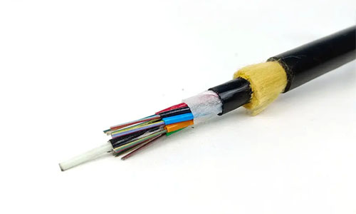 ADSS Fiber Optic Cable
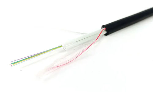 ASU Fiber Optic Cable
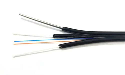 FTTH Fiber Optic Cable
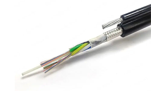 Figure 8 Fiber Optic Cable
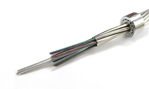 OPGW Fiber Optic Cable
 Coaxial Cable
 Ethernet Cable
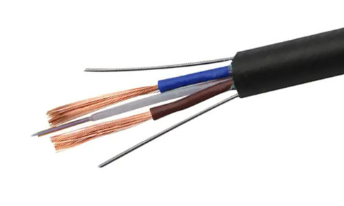 Photoelectric Composite Fiber Optic Cable
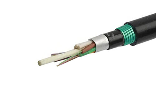 Underground & Pipeline Fiber Optic Cable
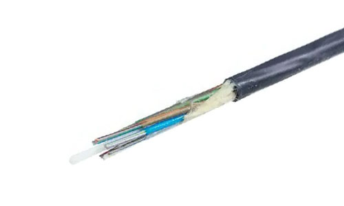 Air-Blown Micro Fiber Optic Cable
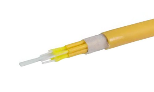 Indoor Fiber Optic Cable
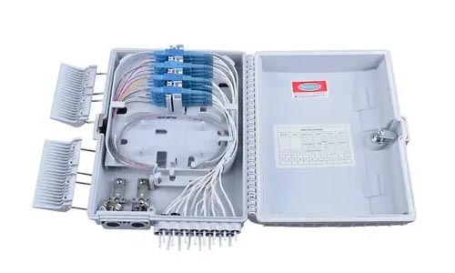 Fiber Optic Distribution Box
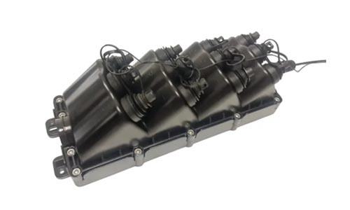 Multiport Service Termina Box
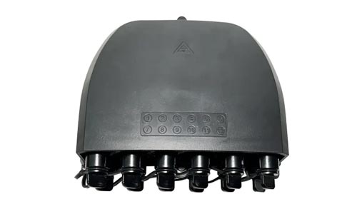 Fiber Optical Terminal Box
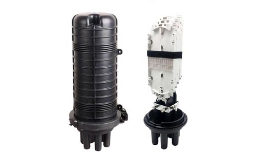 Fiber Optic Splice Closure
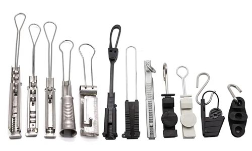 Fiber Optic Clamps
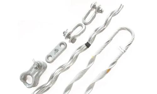 Fiber Optic Cable Fittings
 ADSS Fiber Cable
 ASU Fiber Cable
 OPGW Fiber Cable
 FTTH Fiber Cable
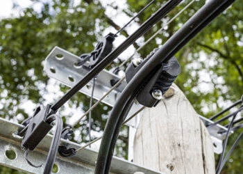 Figure 8 Fiber Cable
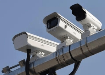 Photoelectric Composite Fiber Cable
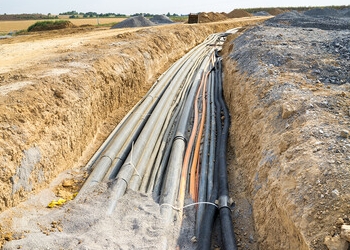 Underground & Pipeline Fiber Cable
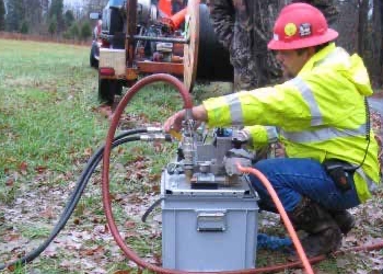 Air-Blown Micro Fiber Cable
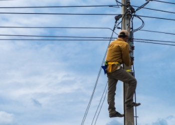 Aerial Fiber Cable
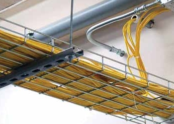 Indoor Fiber Cable
 Fiber Optical Terminal Box
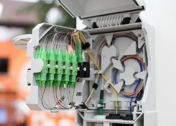 Fiber Optic Distribution Box
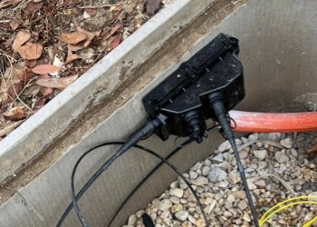 Multiport Service Termina Box
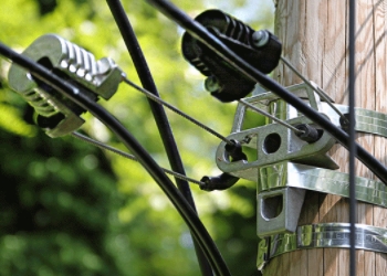 Fiber Optic Clamps
 About Us
 Our Team
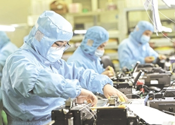 History
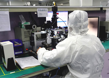 R&D Strength
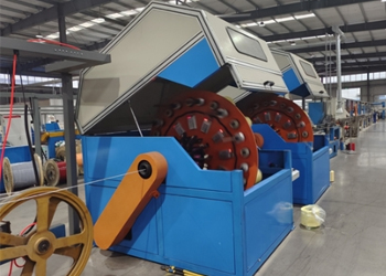 Production Base
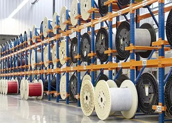 Warehouse & Logistics
 Quality
 FAQs
FAQsFiber Optical Splitter Fundamentals
Contact for Free Quotation & Sample, According to your needs, customize for you.
inquiry nowFiber Optical Splitter Fundamentals
A fiber optical splitter is an optical device that divides one optical signal into multiple signals. Commonly deployed in fiber optic networks, it assists in distributing a single fiber line across multiple users. There are several types of fiber optical splitters, such as planar lightwave circuit (PLC) and fused biconical taper (FBT), each with its advantages. For instance, PLC splitters are great for big networks and FBT splitters suit smaller ones. These splitters support data speeds and stable signals over long distances, making them crucial for high-speed internet and TV. A lot of today’s networks rely on splitters to maintain connections that are seamless and dependable. The next piece will demonstrate how splitters function and where to apply each variety.

What is a Fiber Optical Splitter?
A fiber optic splitter is a passive component in optical networks that plays a crucial role in dividing an input signal into two or more outputs. This mechanism allows a signal from a single mode fiber to access multiple destinations, significantly reducing the amount of cabling required. PLC fiber optic splitters link backbone frames to terminal equipment, ensuring subscribers at residences, offices, and large complexes receive reliable connectivity. You’ll encounter these splitters in many PONs such as GPON and FTTH, where they enable signal branching while consuming minimal energy. Optical fiber splitters extend network reach and maintain smooth operations for more users.
1. Core Function
Fundamentally, a fiber optical splitter splits optical power from one into many. That way, one powerful light signal could serve multiple homes all at the same time, such as in apartment buildings or urban settings. It’s the equivalent of taking one flashlight and shining it through a prism—now you have multiple light beams lighting up separate rooms.
Maintaining the signal quality during the split is what matters. Good splitters are designed to prevent too much signal loss, so all of you get a nice crisp feed. If a splitter isn’t high quality, certain users could get slow speeds or dropouts. When designed carefully, splitters assist networks in reaching more individuals without decreasing quality.
2. PLC vs. FBT
There are two main types: Planar Lightwave Circuit (PLC) and Fused Biconical Taper (FBT). PLC splitters utilize a quartz base and are produced using chip technology, making them perform better for higher output counts, such as 1x16 or 1x32 arrangements. They’re optimal for larger networks as they maintain low losses and equalize signals across all outputs.
FBT splitters are formed by heating and fusing fibers together, so the cost remains low for small splits such as 1x2 or 1x4. They’re basic and excellent for tiny projects, but don’t navigate multiple splits as cleanly as PLC does. When choosing one, consider how many splits you require and the tradeoff between cost and performance.

3. Splitting Ratios
Splitting ratio is the amount of signal each output gets. To use as an example, a 1×2 sends half the power to each line and a 1×4 gives a quarter to each. Networks can choose from 1x2, 1x4, up to 1x64, based on how many subscribers need to be served from one source.
Selecting appropriate split ratios optimizes network performance. A bustling office may require a 1x8, but the occasional home user would make do with a 1x2. For instance, city-wide FTTH networks use big splitters to get to many homes from one point, squeezing maximum juice from each cable.
4. Network Role
Fiber optical splitters allow networks to expand with a minimum of additional cabling.
They make it easy to add more users.
Splitters let many people use one strong network.
They keep data moving smooth, even over long distances.
Key Performance Metrics
Fiber optic splitters are the cornerstone of strong networks, particularly when it comes to optical transmission efficiency. Selecting the appropriate plc fiber optic splitters involves examining key metrics that determine the configuration's effectiveness. These figures help compare goods and choose the most suitable option for every task, from wide-area networks to household internet.
| Metric | What It Measures | Why It Matters | Typical Value/Range |
|---|---|---|---|
| Splitting Ratio | How input power splits to each output | Affects signal strength, coverage | 1:2, 1:4, 1:8, 1:16, etc |
| Insertion Loss | Signal loss from input to output (dB) | Lower means more efficient network | 0.2–1.2 dB |
| Uniformity | Power difference among outputs (dB) | Key for stable performance | <1.0 dB (good) |
| Isolation | Signal leakage between channels (dB) | Higher means less cross talk | >40 dB |
| Directivity | Ratio of forward to reverse leak (dB) | Higher is better for signal flow | >55 dB |
| Excess Loss | Additional loss besides theoretical (dB) | Impacts total signal budget | 0.2–1.2 dB |
| Temp. Range | Operating temperature (°C) | Needed for harsh environments | -40 to 85°C |
Insertion Loss
Insertion loss indicates how much signal is lost as light passes through the splitter. This is measured in decibels (dB) and provides an immediate feel for network performance. If the loss is high, your signal is weak which can impact data quality and limit the reach of your network.
Connector quality and fiber alignment really do make a difference. Bad connectors or misaligned fibers would add even more loss. For instance, cheap splitters with shoddy connectors might exhibit 1.5 dB loss, while quality ones remain below 1 dB. It’s smart to keep insertion loss low in high-speed, long-range links. Go for splitters with the least insertion loss possible–especially for business or telecom networks.
Return Loss
Return loss is a parameter that measures how much signal is reflected back to the source rather than propagated onward. Higher return loss (dB) is better. That’s less thinking, which keeps your network humming.
A good return loss is typically over 55 dB. Higher values reduce the likelihood of packet loss and jitter, which is critical in video streaming or voice calls. To increase return loss, employ angled connectors and ensure the fiber end faces are clean and well-polished.
Uniformity
Uniformity tests whether all output ports receive an equal power allocation. If the power’s off balance, a couple of those devices might snag weak signals. That’s typically an issue in FBT splitters, particularly in large splits such as 1×8. Bad uniformity = some users receive slow connections or dropped data.
For optimal performance, seek out splitters with under 1 dB variance between outputs. The constant power keeps internet, TV or phone signals stable for all users. Always verify specs pre-purchase, particularly for big networks servicing numerous users.
Directivity
Directivity is about preventing signals from leaking backward into the system. Highly directive (in excess of 55 dB), which means decreased likelihood of interference from backpropagating signals.
Splitters with high directivity keep your network clean and free of cross talk. This is essential for data centers or telecom hubs where thousands of signals ride side-by-side. Choose splitters with quality directivity for any task where crisp routing counts.
Manufacturing and Quality
Fiber optic splitter components, such as plc fiber optic splitters, constitute a significant portion of today’s data networks, and their manufacturing process determines their performance characteristics. Good manufacturing provides optical fiber splitters that last longer, preserve signal strength, and integrate with multiple types of systems. Selecting the right materials, adhering to rigorous standards, and testing every splitter with rigorous tests all contribute to ensuring the devices perform the task they’re designed for.
Material Science
Most splitters employ quartz or silica as they’re both transparent and strong, allowing light to be transmitted with minimal attenuation. A few new splitters at this point make use of special glass blends or coatings to reduce signal loss and increase durability.
The type of fiber picked is important—combining different fibers can lead to increased loss or even poor splits. When premium materials are used, splitters can take the stronger signals without falling apart, even after years in hard places.
High-end R&D in material science, such as new coatings that reduce dust and scratches, can boost splitter performance. This aids in dusty locations or environments with large temperature fluctuations.
Fabrication Process
Building a fiber optical splitter isn’t easy. There are two main ways: FBT (fused biconical taper) and PLC (planar lightwave circuit). FBT splitters twist and melt 2 fibers together, which makes them a great choice for small splits but not near as many branches. PLC splitters employ lithography, similar to fabricating microchips, so it’s simpler to generate multiple branches simultaneously.
Accuracy is immense in both techniques. If the twist or etch is off even a little bit, the splitter may not perform properly – signal loss spikes, or branches won’t split evenly. That’s why corporations continue to strive for improved machines and clarified steps, which further reduces costs and enables wider adoption.
Testing Protocols
-
Visual Inspection: Each splitter gets checked for cracks, dust, or defects under a microscope before moving on.
-
Insertion Loss Testing: Measures how much signal is lost—recorded in decibels (dB)—for each output port, since low loss means better quality.
-
Return Loss Testing: Shows how much light bounces back toward the source, which can mess with upstream signals.
-
Uniformity Test: Looks for even signal split across all ports. If a single port gets significantly less, that’s a fail.
-
Isolation Check: For big networks, isolation over 40 dB is needed to stop signal bleed between ports.
Frequent testing of fiber optic splitters — not only at the fiber end but throughout the process. This catches issues early, ensuring only the finest plc fiber optic splitters make it to the field, satisfying customers across the globe.
Fiber Handling and Preparation
Fiber handling and preparation is essential to maintaining fiber optic splitters. Errors tend to cause elevated signal loss, reduced lifespan, or even outright failure. Fiber splitters—be they FBT-made or PLC tech—rely on clean, accurate work all the way through—from fusing and tapering fibers to sealing against moisture when outside. All three—the input/output fiber arrays and the chip—need to be carefully configured on the aligner stage for optimal performance. Look at connector type (LC, SC, FC) and splitting configuration (1xN, 2xN) as both influence how signals are split and routed.
Best practices for cleaving, cleaning, and inspecting fibers:
-
Use clean, sharp cleaving tools at all times, or you’ll get poor breaks.
-
Wipe fiber ends with lint-free wipes and fiber-safe cleaning solutions.
-
Inspect end faces with a specialized scope before connecting.
-
Never bend fibers beyond their rated minimum bend radius.
-
Seal all exposed fibers if used outdoors to prevent moisture intrusion.
-
Store unused fibers in dust-free cases.
Cleaving
Cleaving involves fracturing an optical fiber at a specific angle to achieve a flat, smooth end face. This step is the foundation for quality splicing or connectorization. A clean cleave not only helps maintain low signal loss, but ensures the splitter functions properly.
Proper method involves scoring the fiber with a diamond or carbide blade, and then lightly snapping it. I found that automatic cleaver provides the best, most repeatable results. Bad cleaving results in rough, angled ends, which in turn cause high insertion loss and low return loss—two specs that indicate how efficiently the splitter transmits light. Bad cleaving can render splitters useless and slurry their lives.
Cleaning
Fiber end cleaning is not only best practice — it’s a necessity in any network. Dust, oil or moisture can occlude light and interfere with signals. Even the smallest speck can increase insertion loss and decrease signal strength.
Lint-free wipes, isopropyl alcohol, or pre-moistened fiber wipes work great to clean fiber tips. There are special fiber cleaning pens that are good for connectors. Always wash prior to examination and after touching.
Skipping cleaning can cause weak signals and bad network speed. Over time, this can erode the splitter and result in its failure.
Inspection
Inspection refers to examining fiber end faces for cracks, chips, or debris prior to installation. A fiber scope or video microscope allows you to identify issues before they turn into a problem.
Frequent inspections assist in identifying problems such as end face scratches or contamination, which can generate increased insertion loss or damage directivity. Detecting trouble upfront saves time and money by preventing poor installations.
Good inspection is the key to top quality in every fiber optic network.
Unseen Damage Mechanisms
Optical splitters, the core of passive optical LANs, encounter numerous threats to long-term reliability. Damage can be invisible until it results in signal loss or network downtime. Understanding the unseen damage mechanisms aids in keeping fiber networks robust and performing optimally.
Common unseen damage mechanisms in optical fibers:
-
Photodarkening (solarization) in germanium-doped core fibers under UV or short wavelength visible light.
-
Adhesive dissolving and glass cracking in extreme heat or moisture.
-
Contamination during assembly, leading to hidden flaws.
-
Connector stress from bending or tension.
-
Interface damage at connection points.
-
Environmental effects, like temperature swings or chemical exposure.
-
Principle: Stress rods in PM fibers causing core changes
Knowing about these issues allows network owners to take action to prevent minor problems from becoming major malfunctions. Preventive maintenance and routine inspections prevent expensive damage and insure that networks hum along nicely.
Intrinsic Thresholds
Intrinsic thresholds are the internal fiber performance ceilings—how much light, heat, or strain the fiber can withstand before it begins to fail. Each fiber type has individual limits, usually characterized by the glass and coating.
If these boundaries are crossed, connection dropouts, increased error rates, or even failure may occur. For instance, photodarkening creeps unnoticed in UV-irradiated fibers, gradually diminishing signal power. PM couplers may lose PER at cold temperatures because of adhesive contraction.
Monitoring working conditions keeps them safe. Monitoring tools to detect emerging loss or temperature keeps you ahead of trouble. Threshold alarms and choosing fibers with higher thresholds are smart.
Interface Damage
Interface damage occurs where fibers meet—at splitters, joints, or connectors. Even a minuscule scratch or dust speck can occlude or diffract light.
Poor handling or rushed installs just makes it worse–resulting in performance or signal drops. Cheap splitters and connectors can add to the danger, rendering networks less robust with the passage of time.
Using quality connectors reduces the potential for unseen damage mechanisms. Wiping contacts before locking them in aids. Clear rules for plugging and unplugging fibers ensure no shortcuts are given.
Connector Stress
Connector stress is the key to how much bending or pulling a fiber can endure, particularly where it plugs in. Excessive pressure results in either fractured glass or broken connectors. Sometimes all you get is random signal drops you can’t seem to pin down.
Correct install methods—no sharp bends, no hard pulls—do a lot. Strain reliefs, like soft boots or cable ties, assist in distributing tension so connectors remain secure over time.
Environmental Factors
Heat, humidity, chemicals — they all chip away at fiber health. Hot, moist patches can even degrade adhesives or make glass crack more quickly. Some enclosures are moisture and dust proof, which can make a huge difference in long-term survival.
Picking the right materials for the task, and confining fibers in rugged encapsulations, helps keep out most dangers. Fiber inspections during routine upkeep catches issues early, before they bring the network down.
The Splitter's Hidden Impact
Fiber optic splitters, particularly plc fiber optic splitters, have a silent but profound impact on the dynamics of network expansion, evolution, and resilience in the digital era. These mini monsters sometimes get overlooked, but their impact on network architecture, energy consumption, and future-proofing is immense. A closer look shows why thinking splitter first is essential for durable, adaptable, and dependable networks.
Network Scalability
Network scalability indicates the network can expand as additional data and users arrive.
Fiber optical splitter enables a single fiber to serve multiple endpoints. For example, in a business park or a city block, splitters allow a single primary fiber to extend to tens of buildings or residences. That is, you don’t have to run literally hundreds of cables–1 cable, many splits. The split ratio, like 1:4 or 1:32, tells you how many ways the signal is shared. High split ratios enable you to reach more users, but can result in more signal loss, so the tradeoff is important. Carefully constructed growth networks save time and expenses down the road. If you use the proper type—FBT for splits less than 1x4, PLC for in excess of 1x8—the network expands seamlessly and remains reliable.
Budgeting Power
Power budgeting ensures signal strength is sufficient for all users post-split.
Splitters can create insertion loss, which is to say the signal degrades with every split. If the power budget isn’t right, the network can slow or even die. Low-quality splitters, especially in large splits like 1:32, can cause big losses or fail more often. To control this, utilize quality splitters with less than 0.5 dB imbalance. Watch the split ratio as well as fiber length. Cheap splitters save you money now and end up costing you more in repairs and downtime.
Future-Proofing
Constructing networks that endure is future-proofing.
Opting for splitters that are tunable in terms of splitting ratio and wide bandwidth, from 20 to 640 nm, ensures the network can adapt to shifts in speed and technology. As new devices and applications require additional bandwidth, splitters that facilitate upgrades will maintain the network’s preparedness. Thinking ahead to upgrades pays off in dollars and frustration later. Good splitters reduce failure and keep the network robust as technology advances.
The Role in Emerging Tech
Splitters enable smart cities, 5G and gigabit internet.
They assist in distributing signals for video calls, cloud and smart home devices. Choosing the appropriate splitter style and quality minimizes potential points of failure and reduces expenses as new technology deploys.
Conclusion
Fiber optical splitters have a significant role in the transmission of data and connectivity. It’s these little guys that mold the velocity and coverage of networks we consume daily. A quality splitter maintains signal strength and helps reduce bottlenecks. Tiny little errors in manufacturing or handling can result in actual service degradation, so attention to detail in this area really rewards. You’ll catch splitters in dense urban bundles or nestled within country lines. All of them assist in staying connected anywhere. To optimize performance in a network, check the condition of every splitter. Tell your own splitter tales or inquire further–a lot of people experience the same bruises and celebrations in this crazy-busy arena.
Frequently Asked Questions
What is a fiber optical splitter?
A fiber optic splitter, particularly the plc fiber optic splitters, is essentially a device that splits an optical signal into several, making it popular in fiber optic networks to distribute bandwidth to multiple endpoints.
How does a fiber optical splitter affect signal quality?
A fiber optic splitter introduces a certain degree of signal attenuation, or insertion loss. High-quality plc fiber optic splitters reduce this loss, ensuring dependable optical transmission and data delivery throughout the network.
What are the key performance metrics for fiber optical splitters?
Important parameters such as insertion loss, uniformity, return loss, and splitting ratio dictate how well the fiber optic splitters deliver optical signals reliably.
Why is manufacturing quality important for fiber optical splitters?
Manufacturing quality affects the durability and longevity of plc fiber optic splitters. Quality fabrication minimizes signal loss and allows accurate splitting, facilitating reliable optical transmission for network operation.
How should fiber optical splitters be handled and prepared?
Dirt and scratches on the optical fiber splitter are avoided by careful handling; employ clear instruments and install methodologies to preserve efficiency.
What are some common unseen damage mechanisms for fiber optical splitters?
Unseen damage, such as micro-cracks and contamination, can impair the quality of the fiber optic signal, especially in optical fiber splitters.
What is the hidden impact of using a low-quality fiber optical splitter?
Bad fiber optic splitters can lead to more signal loss, increased maintenance, and disastrous network failures. Investing in quality plc fiber optic splitters fosters network stability and long-term savings.