 Optical Fiber
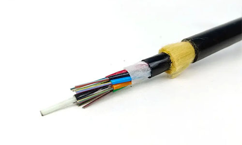 ADSS Fiber Optic Cable
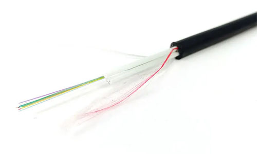 ASU Fiber Optic Cable
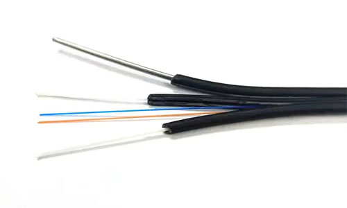 FTTH Fiber Optic Cable
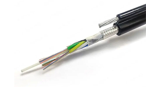 Figure 8 Fiber Optic Cable
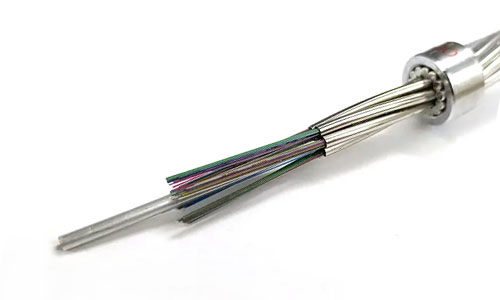 OPGW Fiber Optic Cable
 Coaxial Cable
 Ethernet Cable
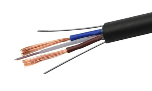 Photoelectric Composite Fiber Optic Cable
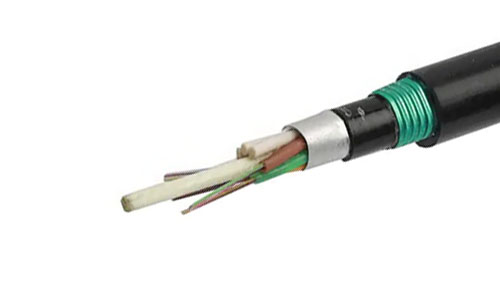 Underground & Pipeline Fiber Optic Cable
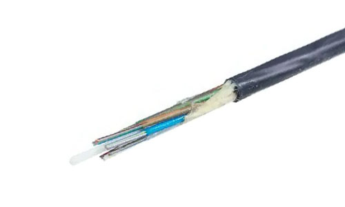 Air-Blown Micro Fiber Optic Cable
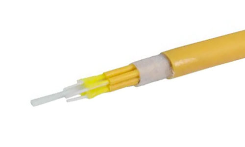 Indoor Fiber Optic Cable
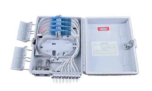 Fiber Optic Distribution Box
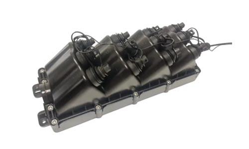 Multiport Service Termina Box
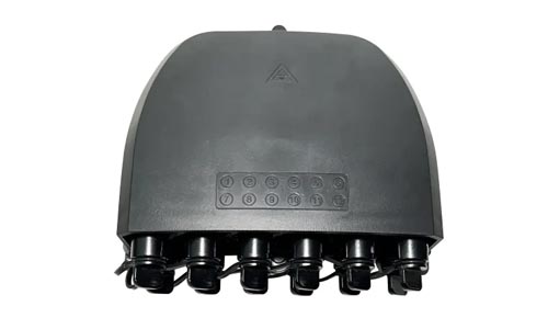 Fiber Optical Terminal Box
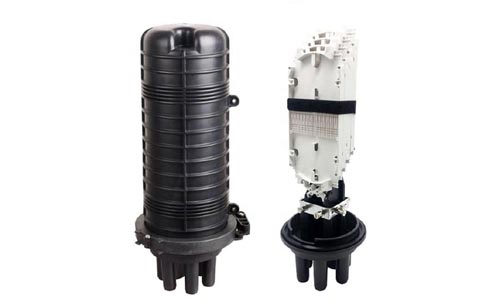 Fiber Optic Splice Closure
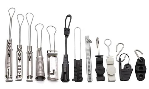 Fiber Optic Clamps
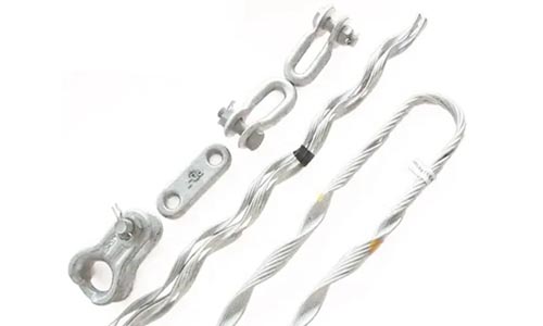 Fiber Optic Cable Fittings
 ADSS Fiber Cable
 ASU Fiber Cable
 OPGW Fiber Cable
 FTTH Fiber Cable
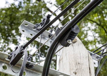 Figure 8 Fiber Cable
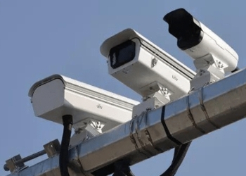 Photoelectric Composite Fiber Cable
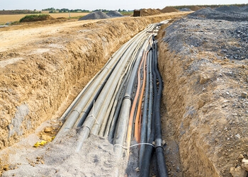 Underground & Pipeline Fiber Cable
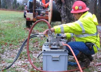 Air-Blown Micro Fiber Cable
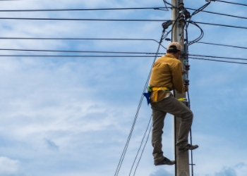 Aerial Fiber Cable
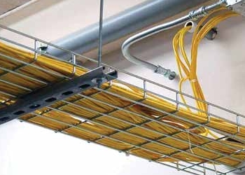 Indoor Fiber Cable
 Fiber Optical Terminal Box
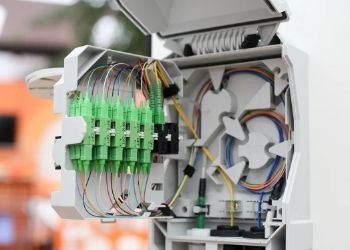 Fiber Optic Distribution Box
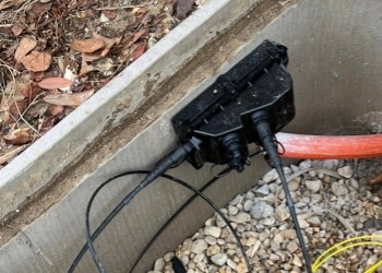 Multiport Service Termina Box
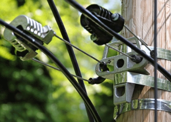 Fiber Optic Clamps
 About Us
 Our Team
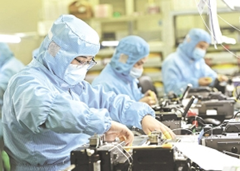 History
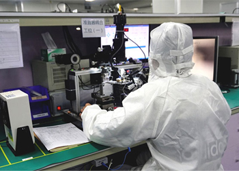 R&D Strength
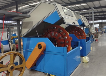 Production Base
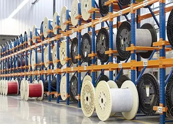 Warehouse & Logistics
 Quality
 FAQs
FAQsApplications of Figure 8 Fiber Optic Cable
In the rapidly evolving world of telecommunications and network infrastructure, the demand for robust, cost-effective, and easy-to-install cabling solutions has never been higher. Among the myriad of options available, the Figure 8 Fiber Optic Cable stands out as a versatile and widely adopted choice, particularly for aerial installations. This comprehensive guide delves into the intricacies of Figure 8 fiber optic cables, exploring their unique structure, diverse applications, technical specifications, and advantages.

What is a Figure 8 Fiber Optic Cable?
A Figure 8 fiber optic cable, also known as a self-supporting aerial cable, is characterized by its distinctive cross-sectional shape resembling the number "8". This design integrates two key components into a single, cohesive unit:
-
The Messenger Section: The upper loop of the "8" typically consists of a steel wire or a stranded steel messenger. This component provides the necessary mechanical support and tensile strength, allowing the cable to be strung between poles or other structures without the need for additional support wires.
-
The Optical Cable Section: The lower loop houses the optical fibers themselves, protected within a loose tube or a stranded core, surrounded by strength members and a protective sheath.
This integrated design simplifies installation, reduces labor costs, and enhances the overall reliability of aerial fiber deployments. Common types include GYTC8S, GYTC8A, and GYXTC8S, each tailored for specific environmental conditions and fiber counts.
Structural Overview and Key Components
Understanding the anatomy of a Figure 8 fiber optic cable is crucial for appreciating its performance capabilities. Let's break down its primary elements:
1. Messenger Wire Options
The messenger wire is the backbone of the cable's self-supporting capability. Options include:
-
Single Steel Wire Messenger: Lightweight and suitable for shorter spans (under 80-100 meters).
-
Stranded Steel Wire Messenger: Composed of multiple galvanized steel wires (e.g., 7x0.3mm, 7x1.0mm), offering superior tensile strength for long spans and areas prone to high wind or ice loads.
-
FRP (Fiber Reinforced Plastic) Messenger: A non-metallic alternative, ideal for areas with high lightning risk or where electrical isolation is required.
2. Optical Cable Core Structures
The optical fibers are protected within the lower section of the "8". Common core designs are:
-
Central Loose Tube (e.g., GYXTC8S): Fibers are housed in a single central loose tube filled with water-resistant gel. Available in armored (with corrugated steel tape for rodent and crush protection) and non-armored versions.
-
Layer-Stranded (e.g., GYTC8S/GYTC8A): Multiple loose tubes, each containing fibers, are stranded around a central strength member. This allows for higher fiber counts (up to 144 cores or more) and better mechanical balance, making it suitable for backbone networks.
3. Protective Layers and Materials
-
Loose Tube Material: High modulus plastic, resistant to hydrolysis and environmental stress.
-
Water Blocking: Gel filling in loose tubes and water-swelling yarn or tape in the cable core prevent moisture ingress.
-
Moisture Barrier: An Aluminum Polyethylene Laminate (APL) is often applied around the cable core for additional moisture protection.
-
Sheath Materials:
-
HDPE (High-Density Polyethylene): Standard for outdoor use, offering excellent UV resistance and durability.
-
LSZH (Low-Smoke Zero-Halogen): Used in areas where fire safety is paramount, such as near buildings.
-
Flame-Retardant Additives: Enhance fire performance while maintaining flexibility.
-
Technical Specifications and Performance
Figure 8 fiber optic cables are engineered to meet stringent performance standards. Key specifications include:
-
Fiber Count: Ranging from 2 cores for drop cables to 288+ fibers for high-capacity backbone links.
-
Fiber Types: Single-mode (G.652.D, G.657.A1, G.657.A2) for long-distance, high-bandwidth applications, and multimode (OM1, OM2, OM3, OM4) for shorter distances within campuses or data centers.
-
Tensile Strength: Varies based on messenger wire configuration, with short-term tensile strength often ranging from 1,000N to over 10,000N.
-
Operating Temperature: Typically from -40°C to +70°C, ensuring performance in harsh climates.
-
Attenuation: Low signal loss, e.g., ≤0.4 dB/km at 1310nm and ≤0.3 dB/km at 1550nm for G.652.D fibers.
-
Bending Radius: Minimum bending radii (e.g., 20x cable diameter dynamic, 10x static) to prevent fiber damage during installation and operation.
-
Crush Resistance: Ability to withstand external pressure, e.g., 1000N/100mm short term.
Diverse Application Environments
The versatility of Figure 8 fiber optic cables makes them suitable for a wide array of deployment scenarios:
1. Telecommunications and Broadband Access
-
Aerial Telecommunication Backbones: Connecting central offices and distribution points.
-
FTTH (Fiber to the Home) and FTTB (Fiber to the Building): Ideal for last-mile connectivity in residential and commercial areas.
-
Rural Broadband Expansion: Cost-effective solution for extending networks to underserved rural communities.
2. Surveillance and Security Systems
-
CCTV Monitoring: Deploying video surveillance along highways, railways, and in industrial zones.
-
Security Networks: Providing reliable data transmission for security infrastructure.
3. Campus and Industrial Networks
-
Educational Institutions and Corporate Campuses: Connecting buildings within a campus environment.
-
Industrial Facilities: Withstanding harsh environmental conditions in factories and plants.
-
Building-to-Building Connections: Efficiently linking adjacent structures.
4. Infrastructure Projects
-
Power Utility Networks: Using all-dielectric variants (with FRP messengers) along power lines.
-
Railways and Transportation: Communication systems along tracks and in stations.
-
Smart City Initiatives: Supporting the connectivity needs of smart city infrastructure.
Advantages of Figure 8 Fiber Optic Cable
Choosing Figure 8 cable offers several compelling benefits:
-
Simplified and Cost-Effective Installation: The integrated messenger eliminates the need for separate lashing wires and additional hardware, reducing installation time and labor costs by 40-60%.
-
High Mechanical Strength and Durability: Excellent tensile strength, crush resistance, and protection against environmental factors like UV radiation, moisture, and temperature fluctuations.
-
Versatility: Suitable for various spans, fiber counts, and environmental conditions.
-
Reduced Maintenance: Robust design leads to fewer failures and lower long-term maintenance expenses.
-
Improved Aesthetics: A cleaner look compared to cables lashed to separate messenger wires.
Installation Best Practices
Proper installation is key to maximizing the performance and lifespan of Figure 8 cables:
-
Pre-Installation Planning: Conduct thorough site surveys to assess span distances, pole conditions, clearance requirements, and environmental factors like wind and ice load.
-
Messenger Wire Attachment: Use appropriate suspension hardware designed for Figure 8 profiles.
-
Tension Management: Maintain correct tension—too tight can damage fibers; too loose causes excessive sag. Use tensioning tools and follow manufacturer guidelines.
-
Deployment Tools: Employ cable rollers and guides that support both sections of the "8" to prevent kinking or stress.
-
Cable Bending: Adhere to minimum bend radius specifications during installation and when securing the cable to poles.
-
Grounding: Properly ground metallic messenger wires to protect against lightning strikes and induced voltages.
-
Splicing and Termination: Use qualified technicians and appropriate splicing enclosures and connectors to ensure low insertion loss.
Conclusion
The Figure 8 Fiber Optic Cable is a cornerstone of modern aerial fiber optic networks, offering a blend of mechanical strength, installation efficiency, and cost-effectiveness. Its unique design caters to a wide range of applications, from rural broadband expansion to urban telecommunication backbones. By understanding its structure, specifications, and benefits, businesses and individuals can effectively leverage this technology and ensure their valuable content reaches those seeking information and solutions in this domain. As the demand for high-speed connectivity continues to grow, the Figure 8 cable will undoubtedly remain a vital component in building the infrastructure of the future.