 Optical Fiber
 ADSS Fiber Optic Cable
 ASU Fiber Optic Cable
 FTTH Fiber Optic Cable
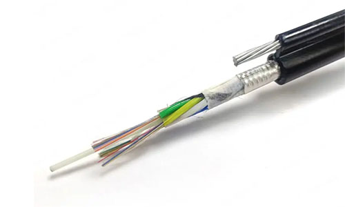 Figure 8 Fiber Optic Cable
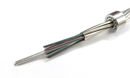 OPGW Fiber Optic Cable
 Coaxial Cable
 Ethernet Cable
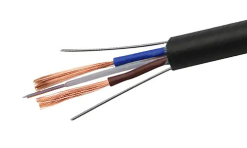 Photoelectric Composite Fiber Optic Cable
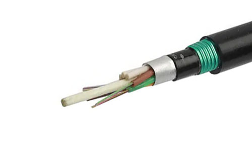 Underground & Pipeline Fiber Optic Cable
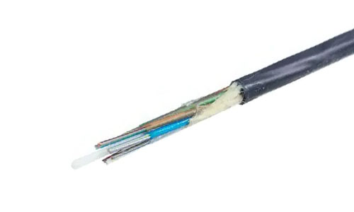 Air-Blown Micro Fiber Optic Cable
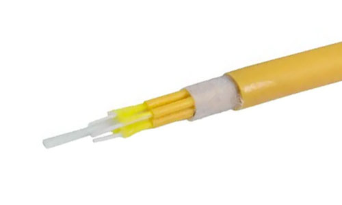 Indoor Fiber Optic Cable
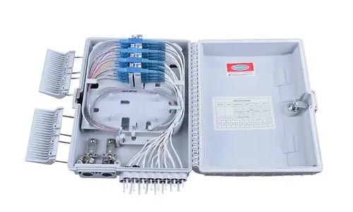 Fiber Optic Distribution Box
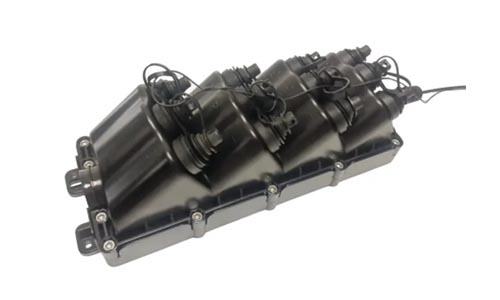 Multiport Service Termina Box
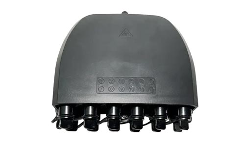 Fiber Optical Terminal Box
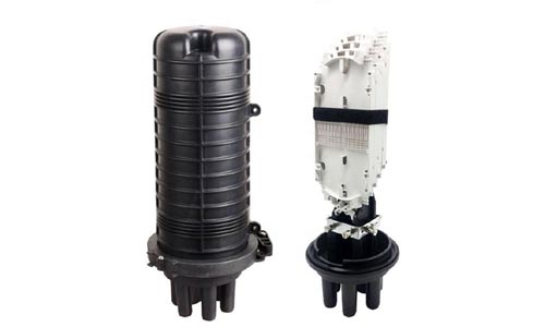 Fiber Optic Splice Closure
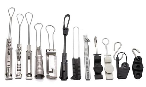 Fiber Optic Clamps
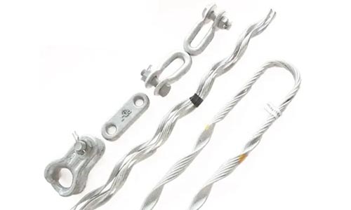 Fiber Optic Cable Fittings
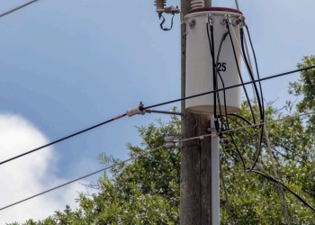 ADSS Fiber Cable
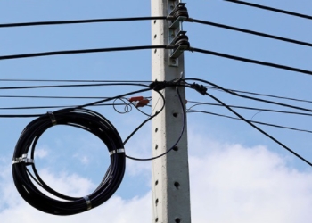 ASU Fiber Cable
 OPGW Fiber Cable
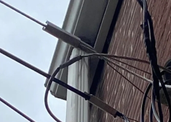 FTTH Fiber Cable
 Figure 8 Fiber Cable
 Photoelectric Composite Fiber Cable
 Underground & Pipeline Fiber Cable
 Air-Blown Micro Fiber Cable
 Aerial Fiber Cable
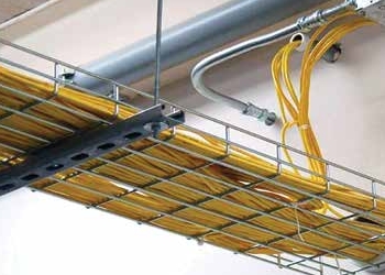 Indoor Fiber Cable
 Fiber Optical Terminal Box
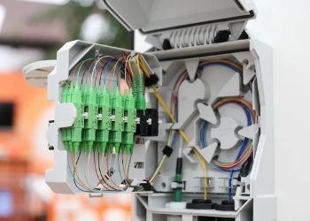 Fiber Optic Distribution Box
 Multiport Service Termina Box
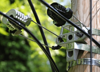 Fiber Optic Clamps
 About Us
 Our Team
 History
 R&D Strength
 Production Base
 Warehouse & Logistics
 Quality
 FAQs
FAQsA Comprehensive Analysis of Six Major Optical Communication Wavebands
2026-06-04
Optical fiber realizes signal transmission via total internal reflection of infrared light inside silica core. Restricted by intrinsic silica absorption loss, Rayleigh scattering, infrared absorption and hydroxyl water peak attenuation, six mainstream commercial wavebands are standardized in the global optical communication industry: 850 nm, 1310 nm, 1383 nm, 1490 nm, 1550 nm and 1625 nm. These wavelengths cover short-range LAN, metropolitan network, long-haul backbone, PON fiber access, optical amplification and optical fiber testing scenarios. Distinct differences exist in attenuation coefficient, chromatic dispersion, maximum transmission distance, matching optoelectronic components and fiber selection among different wavebands, which serve as fundamental criteria for fiber specification selection, engineering design and optical component R&D. This paper consists of three core sections: detailed optical characteristics of six wavebands, horizontal comparison of core fiber technical specifications, and matching fiber & practical application classification for each wavelength.

Chapter 1 Detailed Optical Characteristics of Six Classic Fiber Communication Wavebands
1.1 850 nm (Short-wavelength Window, First Optical Communication Window)
850 nm is the earliest commercialized communication wavelength exclusively deployed for multimode optical fiber. Its dominant loss source derives from Rayleigh scattering, whose attenuation is inversely proportional to the fourth power of wavelength. Due to short optical wavelength, typical fiber attenuation ranges from 2.5 to 3.0 dB/km, the highest loss level among six wavebands. No zero-dispersion point exists at 850 nm; combined material dispersion and intermodal dispersion severely broaden optical pulses and limit transmission reach. For OM1 and OM2 multimode fiber, the maximum reach of Gigabit Ethernet is 550 m and 220 m respectively at 850 nm, while 10G Ethernet only supports 33 m (OM1) and 82 m (OM2).
Vertical-Cavity Surface-Emitting Lasers (VCSELs) are standard light sources for this band with compact packaging, low cost and no extra cooling requirement. Low coupling difficulty greatly reduces system construction cost. Limited by high attenuation and dispersion defects, 850 nm is confined to indoor short-distance cabling, widely adopted in data center interconnection and structured cabling systems.
1.2 1310 nm (Zero-Dispersion Window, Second Communication Window)
Regulated by ITU-T standard, 1310 nm is the benchmark zero-dispersion wavelength for G.652 single-mode fiber. Material dispersion counteracts waveguide dispersion at this band, generating near-zero chromatic dispersion around 0 ps/(nm·km) and eliminating pulse distortion caused by dispersion without extra dispersion compensation modules. The intrinsic fiber attenuation falls to 0.33~0.38 dB/km with no obvious hydroxyl water peak absorption, making it the preferred option for point-to-point passive optical transmission.
Fabry-Perot (FP) laser is the mainstream emitter for 1310 nm with moderate component cost. However, this wavelength falls outside the gain spectrum of EDFA (Erbium-Doped Fiber Amplifier), so long-distance transmission relies on electrical-optical regeneration relay instead of all-optical amplification. Besides service transmission, 1310 nm is the default test wavelength for OTDR (Optical Time Domain Reflectometer), universally used for fiber cable construction acceptance and fault location.
1.3 1383 nm (Water-Peak Window, Low-Water-Peak Optimized Band)
Conventional G.652A/B single-mode fiber contains residual OH⁻ ions from preform fabrication, creating strong absorption peak at 1383 nm with attenuation over 20 dB/km, which made this wavelength unavailable for commercial use decades ago. Thanks to advanced dehydration and synthetic preform technology for low-water-peak G.652C/G.652D fiber, residual hydroxide ion concentration is controlled at ppb level, cutting water peak loss below 0.4 dB/km and enabling large-scale commercial deployment.
Available spectrum covers 1360~1410 nm, filling the frequency gap between 1310 nm and 1490 nm for CWDM channel expansion. Similar to 1310 nm, 1383 nm cannot be amplified by EDFA, restricting its application to short-reach metropolitan CWDM expansion and private security monitoring network. Typical attenuation is maintained at 0.38~0.42 dB/km.
1.4 1490 nm (S-band Starting Point, Downstream Core Wavelength for FTTH PON)
Belonging to S-band (1460~1530 nm), 1490 nm is defined as the standard downstream wavelength of EPON/GPON under ITU-T G.984 protocol: OLT transmits downstream data at 1490 nm, while ONU sends upstream return signal at 1310 nm, realizing single-fiber bidirectional transmission via wavelength division multiplexing.
Typical attenuation of 1490 nm ranges from 0.26 to 0.30 dB/km, superior to 1310 nm in loss performance; chromatic dispersion stays around 10 ps/(nm·km), supporting 20 km standard PON ODN trunk without dispersion compensation. DFB laser with narrow spectral linewidth and constant-temperature control is equipped for weak signal transmission after passive optical splitting. Matched WDM filter isolates upstream and downstream signals, making 1490 nm the most widely used wavelength for global fiber-to-home broadband access.
1.5 1550 nm (C-band Core, Lowest Loss Third Communication Window)
Known as the golden window of optical communication, 1550 nm locates in C-band (1530~1565 nm), where silica fiber reaches its intrinsic minimum attenuation of 0.19~0.22 dB/km across all six wavebands. This wavelength perfectly matches the gain spectrum of EDFA; dozens of DWDM optical carriers can be amplified simultaneously without optoelectronic regeneration, enabling thousands of kilometers repeater-free long-haul transmission.
Standard G.652 fiber presents positive chromatic dispersion around 17 ps/(nm·km) at 1550 nm, requiring DCF (Dispersion Compensation Fiber) for ultra-long DWDM backbone. G.655 non-zero dispersion-shifted fiber retains small residual dispersion (2~6 ps/(nm·km)) to suppress Four-Wave Mixing nonlinear effect, optimized for high-capacity DWDM system deployment. Apart from long-distance backbone, 1550 nm is the exclusive working wavelength for analog CATV RF optical transmission; DWDM system divides C-band into over 80 standardized channels at 0.8 nm spacing for ultra-large-capacity backbone networking and submarine optical cable construction.
1.6 1625 nm (L-band, In-service Fiber Monitoring Wavelength)
1625 nm falls into L-band (1565~1625 nm), mainly designated for real-time online optical fiber monitoring and partial L-band DWDM capacity expansion. Its typical attenuation is 0.23~0.25 dB/km with no water peak interference, and chromatic dispersion reaches approximately 22 ps/(nm·km).
The core advantage lies in spectrum isolation from service wavelengths (1310/1490/1550 nm). Via passive WDM coupler, monitoring light is coupled into working fiber without interrupting running data service; online OTDR based on 1625 nm realizes real-time detection of cable aging, breakpoint and abnormal loss, which becomes the core technology for intelligent O&M of carrier-grade backbone cables. Matched L-band EDFA supports DWDM expansion when C-band spectrum resource is exhausted.
Chapter 2 Core Optical Fiber Technical Parameters & Specification Horizontal Comparison
Optical fiber is categorized into multimode fiber (OM1/OM2/OM3/OM4/OM5) and single-mode fiber (G.652A/B/C/D, G.653, G.655, G.657). Key technical indicators include attenuation coefficient, chromatic dispersion, cutoff wavelength, mode field diameter, macrobending loss and bandwidth.
2.1 Definition of Core Technical Indicators
- Attenuation (dB/km): Optical power consumption per kilometer; lower value represents longer transmission distance, affected by wavelength, raw material and bending status.
- Chromatic Dispersion (ps/(nm·km)): Transmission speed difference between different spectral components; smaller value reduces pulse distortion for high-speed signal.
- Cutoff Wavelength: Critical threshold wavelength for single-mode propagation; only incident light above cutoff wavelength can transmit as single mode inside core.
- Bending Loss: Extra power loss induced by tight fiber bending; G.657 bending-insensitive fiber owns outstanding performance on this index.
- Mode Field Diameter: Effective spot size of propagating light inside single-mode core, directly influencing coupling efficiency between fiber and optoelectronic devices.
- Bandwidth (MHz·km): Core parameter for multimode fiber, determining high-speed short-distance transmission capability.
2.2 Parameter Comparison of Mainstream Fiber Types Across Six Wavebands
2.2.1 Multimode Fiber (850 nm exclusive, partial short-distance 1310 nm compatibility)
Multimode fiber suffers severe intermodal dispersion at 1383/1490/1550/1625 nm and cannot support practical long-distance transmission:
- OM1 (62.5/125 μm): 3.0 dB/km @850 nm, 200 MHz·km bandwidth; 33 m max for 10G Ethernet.
- OM2 (50/125 μm): 2.5 dB/km @850 nm, 500 MHz·km bandwidth; 82 m max for 10G Ethernet.
- OM3/OM4 (Laser-optimized 50/125 μm): OM3:2000 MHz·km, 300 m@10G; OM4:4700 MHz·km,550 m@10G.
- OM5: Dual-window optimized (850 nm+953 nm), customized for short-range 400G data center interconnection.
2.2.2 G.652 Universal Single-Mode Fiber (Full six-waveband compatible for G.652C/D)
- G.652A/B (High water peak): Inapplicable for 1383 nm due to over 5 dB/km absorption loss; 0.35 dB/km & zero dispersion @1310 nm;0.28 dB/km@1490 nm;0.20 dB/km &17 ps/(nm·km)@1550 nm;0.24 dB/km &22 ps/(nm·km)@1625 nm.
- G.652C/D (Low-water-peak): Optimized OH⁻ elimination, below 0.4 dB/km@1383 nm, full six-waveband available, dominant fiber for metro and access network. Cutoff wavelength ≤1260 nm, mode field diameter 9.2 μm, standard bending performance.
2.2.3 G.653 Dispersion-Shifted Fiber
Zero-dispersion point shifted to 1550 nm; near-zero dispersion at C-band while excessive dispersion at 1310 nm, unsuitable for short wavelengths. Severe Four-Wave Mixing restricts its usage in multi-channel DWDM, only for single-wavelength ultra-long private line.
2.2.4 G.655 Non-Zero Dispersion-Shifted Fiber
Slight residual positive dispersion at 1550 nm to balance dispersion compensation and nonlinear suppression, exclusive for C/L-band backbone DWDM and transoceanic submarine cable; poor performance at 1310 nm and below wavelengths.
2.2.5 G.657 Bending-Insensitive Fiber (FTTH Indoor Drop Cable)
Classified into A1 (mild bend optimization) and B2 (ultra-small bending radius); ultra-low loss under tight coiling, fully compatible with six wavebands, standard material for FTTH indoor drop cable and FTTR home wiring.
| Wavelength | 850 nm | 1310 nm | 1383 nm(Low-water-peak) | 1490 nm | 1550 nm | 1625 nm |
|---|---|---|---|---|---|---|
| Typical Attenuation(dB/km) | 2.5~3.0 | 0.33~0.38 | 0.38~0.42 | 0.26~0.30 | 0.19~0.22 | 0.23~0.25 |
Chapter3 Application Scenario, Fiber Selection & System Matching Comparison for Six Wavebands
3.1 850 nm: Data Center & Campus LAN Interconnection
Matching Fiber: OM1~OM5 full-series multimode fiber only Transmission System: Gigabit/10G/25G Ethernet, Fiber Channel storage networking Typical Application: Cabinet patch cord, TOR-to-server short-reach interconnection inside IDC, campus LAN and industrial automation cabling, transmission distance:30 m~550 m Merit & Defect: Low-cost VCSEL source and convenient construction; limited transmission distance, single-mode fiber is mandatory when distance exceeds 550 m.
3.2 1310 nm: Metro Point-to-Point Private Line & Standard Fiber Test
Matching Fiber: G.652 full range & G.657; rarely G.653/G.655 Transmission System: Traditional SDH/MSTP leased line, point-to-point dark fiber access, OTDR fiber acceptance testing Typical Application: Bank inter-city private line, enterprise dedicated optical access, carrier local access network, maximum single-span reach ≤80 km; extra electro-optic relay for longer distance Merit & Defect: Zero-dispersion avoids signal distortion with mature equipment; unavailable for EDFA all-optical amplification, gradually replaced by 1550 nm DWDM for long-haul networking.
3.3 1383 nm: Metro CWDM Low-Cost Spectrum Expansion
Matching Fiber: G.652C/D & G.657 only; invalid for high-water-peak G.652A/B Transmission System: 8/16-channel CWDM coarse wavelength division multiplexing Typical Application: City-level private CATV network, multi-service fiber expansion for industrial park, mine & security monitoring system, max reach ≤40 km Merit & Defect: Efficient spectrum utilization without new fiber laying; no EDFA amplification limits ultra-long-distance deployment.
3.4 1490 nm: Global FTTH PON Fiber Access
Matching Fiber: G.652D for feeder trunk + G.657 for indoor drop cable Transmission System: EPON/GPON/10G PON, single-fiber bidirectional (1490 down,1310 up, 1550 for optional CATV overlay) Typical Application: Residential broadband access, enterprise FTTO full-optical networking, 20 km ODN trunk + within 5 km indoor drop line Merit & Defect: Passive splitter-based centralized OLT deployment, single fiber supports 64~128 end users; becomes foundational infrastructure of global fiber broadband construction.
3.5 1550 nm: Long-Haul DWDM Backbone & CATV Optical Transmission
Matching Fiber: G.652 for metro DWDM, G.655 for national backbone & submarine cable, G.653 for single-wavelength ultra-long private line Transmission System: DWDM dense wavelength division multiplexing, analog CATV RF optical transport, 100G/400G high-speed backbone system Typical Application: Inter-provincial trunk cable, transoceanic submarine optical cable, fiberized CATV HFC network; EDFA-assisted all-optical amplification realizes thousand-kilometer repeater-free transmission Merit & Defect: Minimum fiber attenuation plus mature EDFA technology supports terabit-level single-fiber capacity; high cost for high-end DWDM optical components.
3.6 1625 nm: In-service Cable Monitoring & L-band DWDM Expansion
Matching Fiber: All single-mode fiber types including G.652/G.655/G.657 Transmission System: Online OTDR monitoring platform, L-band DWDM expansion equipment Typical Application: Intelligent real-time patrol for carrier backbone cable, non-interruptive early warning of hidden cable fault, capacity expansion after C-band spectrum saturation Merit & Defect: No occupation of service spectrum to realize non-stop-line monitoring, effectively shorten cable maintenance downtime; mostly deployed for carrier professional O&M network.
Conclusion
Six standard communication wavebands form a layered optical network application system based on inherent silica optical properties: 850 nm dominates short-range indoor multimode cabling;1310 nm acts as fundamental single-mode test and private line wavelength;1383 nm supplements CWDM vacant spectrum;1490 nm monopolizes FTTH passive optical access;1550 nm serves as core of long-haul backbone and CATV transmission;1625 nm specializes in non-interruptive fiber online operation monitoring. Fiber selection follows wavelength-oriented rule: multimode fiber for 850 nm short-range links, G.652D/G.657 for 1310/1383/1490 access network, G.655 non-zero dispersion fiber for 1550 long-haul DWDM, G.657 bend-insensitive fiber for indoor FTTH wiring.
Driven by 5G bearer network construction, large-scale data center high-speed interconnection and FTTR full-home fiber deployment, low-water-peak G.652D and bend-resistant G.657 gradually become mainstream fiber specifications in global optical market. CWDM expansion demand of 1383 nm and L-band 1625 nm keeps growing yearly; 850 nm multimode maintains core position for short-distance high-speed interconnection, while 1550 nm remains irreplaceable golden window for long-haul optical communication relying on mature EDFA amplification technology. Mastering attenuation, dispersion characteristic, fiber matching condition and applicable boundary of six wavebands provides core theoretical support for fiber specification selection, optical network engineering design and existing network capacity optimization.